Tag Archives: disc tractor

China best Agricultural Machinery Farm Machine Parts Light Disc Harrow for Tractor with Free Design Custom

Product Description

Yucheng Hongri Machinery Factory

Product Technical Parameter
Product description:
Name: Agricultural Equipment Mounted Light-duty Disc Harrow for Tractor

1BQX series are used for crushing clods after tillage, preparing soil before seeding, loosening the soil, combining the soil and fertilizer, and cleaning away stubble of plants in light soil field. With reasonable structure, strong ability to rake, durable, easy to use and maintain, etc.

 Model 1BQX-1.1 1BQX-1.3 1BQX-1.5 1BQX-1.7 1BQX-1.9 1BQX-2.3
Working Width (mm) 1100 1300 1500 1700 1900 2200
Working depth (mm) 100-140
No. of disc (pcs) 12 14 16 18 20 24
Diameter Of disc 460mm/ 18inch
Weight (kg) 200 220 240 260 290 350
Linkage Three-pointed mounted
Matched power (hp) 12-15 15-18 25-30 30-35 35-40 55-60

There are 1BQX-1.1, 1.3,1.5, 1.7, 1.9, 2.3 suitable for 12-60 HP tractors
Product Images:

Packing & shipping:

Normal packing or According to your requirement.
Safe, complete and fast delivery of goods to customers

Our Company :

Business type Manufacture
Location Shiliwang Industrial Zone of HangZhou, ZheJiang ,China
Year Established 2003
Occupied area 50 Acres
Company certification CE, ISO9001
Main product disc harrow, disc plough, trailer, boom sprayer , rotary tillers, potato planter ,plowing blade, plough blade, soil-loosening shovel and so on. With good quality, excellent performance, our products annually export to countries around the world, and we have gained the majority of customers trust.

After Service
12 months guarantee of the main parts, we will send the guarantee parts together with the machine in your next order or we can send them by air express if you need it urgently. 

FAQ:

Q: Full price list for these products

A: If you need the price list for these products, please notify the product model so that I can quote you accordingly. Please understand we have a very wide product range, we don’t usually offer full products price list. 

Q: Business terms
A: Shipment time: 25-40 days after your payment
Shipment: By sea
Loading port: HangZhou port, China
Destination port: …To be advised
Payment: T/T, L/C
Warranty: 1 year

Q:How can I order from you?
A: Please send us your enquiry list; we will reply you within 2 working days.

Q:If the finger I look for are not in your catalogue, what should I do?
A: We can develop it according to your drawing or sample.

Q: Why choose Hongri for cooperation? 
A: Comparing with our competitors, we have much more advantages as follows: 

1. More than 30 years in manufacturing farming machine.

2. More Professional Sales staffs to guarantee the better service.
3. More agri machines for your choice.
4. More New products into your range to avoid price competition.
5. Larger quantity production and shipment.
6. Better quality to guarantee better Credit. 
7. Faster delivery time: Only 7 days.
8. More stick quality checking before shipment.
9. More reasonable after-sales service terms.
10. More famous brand: “Hongri” brand and “CE” ceitification.
11. Lower repair rate and bad review rate. 
12. We have American Branch to show our main products. We can give customers best service.

If you have any questions, please feel free to contact me.
 

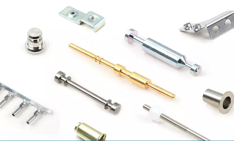
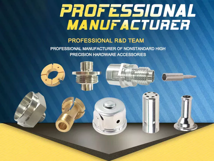
Types of agricultural parts

Agricultural parts can be divided into different categories. These components include tractors, moldboard plows, whips and sickles. Some of the different types of agricultural ingredients are listed below. Each of these parts is important for different types of farming. It is important to know the purpose of each and what it does. If you are a farmer or plan to become a farmer, these parts are critical to your operation.
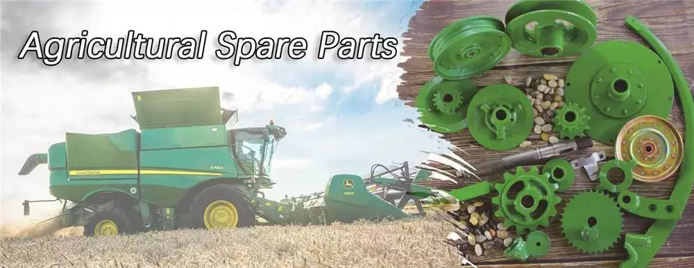
agriculturalparts

Tractor

The first tractor appeared in the 1920s. Ford and International Harvester were among the first companies to produce farm tractors, but the industry has grown rapidly. By the 1920s, hundreds of companies were producing farm tractors. The agricultural depression of the 1930s forced many of these companies out of business. By the 1930s, only 7 companies were major players in the tractor business. Ford produced the largest number of wheeled tractors in the United States between 1930 and 1955.
Some tractors are equipped with various accessories to enhance their performance. These specialized agricultural components are used for a variety of tasks. These include tillage, harvesting, planting and material handling. Tractors vary in horsepower, lift capacity, control and capabilities. Some models also have device mounting options. The downside of this is that if you need to use the tractor for other purposes, you will have to use additional attachments that can damage the tractor.
Modern tractors have a clutch pedal on the gear lever. This allows you to shift quickly without pedaling. Other tractors have a throttle speed button that improves hydraulic flow to the implement. However, the most important component of a tractor is the engine. Tractors must be driven safely because even minor accidents can cause serious damage to farm equipment. While there are many tractors that can operate without these parts, you can find the right tractor for your job.

Shared plows

One of the many uses of shared plows as part of agriculture is to increase the amount of soil in a field. This plow effectively removes compacted soil and lifts weed roots. According to the University of Nebraska-Lincoln Institute for Agriculture and Natural Resources, plowshares are best used in the fall, when weeds are less active and the soil is more fertile.
The basic plowshare can be adjusted by raising or lowering the plowshare to suit runners in the furrow. However, this design is not suitable for breaking up the heavier soils of northern Europe. In the 6th century, however, the advent of the wheel made it possible to use larger moldboards, which increased food production and population growth. Today, farmers in North America have access to a wide variety of moldboard plows.
Agricultural moldboard plows come in 2 basic styles, horse-drawn or tractor-style. Horse-drawn models have 1 bottom, while tractor-pulled moldboard plows have 1 to 14 hydraulically raised bottoms. Other variants include intermediate breakers and twin moldboard plows. Agricultural moldboard plows are often used in the Midwest and elsewhere.

Grass

Grass is used for mowing. The blade is double edged and bolted to the wooden handle. Steel blades are tempered and braced for strength and durability. The blade can be sharpened if necessary. The straw whip is 30 inches long, which can be a good or a bad thing depending on the user’s height. Blades can be sharpened with sandpaper or a file.
The traditional straw whip 32 includes a rear panel and horizontal shelves. It also features a hollow handle with an adapter at the proximal end and a carrying handle at the distal end. The first cable goes to the power supply and goes through the case and handle. After pulling the cable taut, the straw will be firmly attached to the small holder 8.
The suction tube 32 is connected to an electrical connection 47 that powers the device. A battery pack is provided for use away from the tractor. It is a plastic or metal box and consists of 2 parts: a rechargeable battery 67 and a female electrical plug 68. The switch locks in the open position to prevent accidental use. The switch is also equipped with a safety lock button. These 2 components work together to operate the straw.
agriculturalparts

Scythe

Although it is generally believed that the scythe was first developed in Roman times, its actual development may be earlier. Pliny mentioned 2 different types of sickles, Gallic and Roman. The Gallic sickle was the longer of the 2 and was made of mild steel, while the Roman sickle was made of harder, higher carbon steel.
In the past, people cut wheat by hand with a sickle. They replaced scythes and bagging hooks, which required users to bend over to harvest crops. Although they have largely been replaced by tractor machinery, scythes are still used today in parts of Asia and Europe. The sickle can also reach awkward corners, making it more useful in certain types of cuts.
The sickle belt stretches from Europe to the Middle East and the Midwest of the United States and Canada. It also spans most of Russia, the Middle East and North Africa. In the 19th century, Austrian sickle makers dominated the sickle industry. They produced millions of sickles, some dating back to the 1500s. Some of them were exported to India and the former Soviet Union.

Brushcutter

Brushcutters are powerful agricultural tools used primarily for felling and trimming vegetation. These parts are often multifunctional, and some models are even capable of maintaining road edges and ditches. Some models can even trim branches from certain types of trees. Before you buy your own brush cutter, be sure to read the manual carefully and follow the safety rules. For your own safety and the safety of others, please wear a hard hat, eye and hearing protection, padded gloves, long pants, and boots, and keep young children away from work areas.
Brushcutters are usually attached to the tractor via a 3-point linkage system, with the exception of high reach models that are attached to the tractor via fixed stirrups. Additionally, brush cutters often have a balancing mass located opposite the tractor. These agricultural components are complicated to install, but once installed, they remain coupled to the tractor. A brush cutter is a critical piece of equipment on any tractor.
Most brushcutters use hydraulic engines. The power is transmitted mechanically through a PTO (power take-over) mechanism or a cardan shaft, which turns a hydraulic pump. This pump draws hydraulic oil from a special tank and then sends it through a series of distributors to move the arm and the working organ. As a result, the power of the brush cutter is transferred from the tractor to the working organ by a hydraulic engine.
agriculturalparts

Transplanters

Transplanters for agricultural parts are equipment used to plant seedlings into soil. These machines are used in greenhouses and open fields to increase productivity, yield, and the success of harvesting transplanted crops. Transplanters are typically made of steel and are designed to fit seedlings of all shapes and sizes. Buying a used transplanter is a good idea as long as the working parts are in good condition. When considering a used model, you should inspect it for cracks or corrosion and broken parts.
A mechanical transplanter works faster than hand transplanting, but it becomes slower as your quads and back start hurting. Water-wheel transplanters have become popular in recent years. By automatically delivering water into the holes where the transplants are set, water is delivered to the root system without the need for manual intervention. Moreover, water-wheel transplanters save time on watering. John Good, a farmer who uses a water-wheel transplanter, says that speed is no different between a mechanical transplanter and a water-wheel one.

Cultivatorsw

The basic purpose of cultivators is to turn soil and plant matter into a workable form for the crops. Cultivators are used by both large and small farmers. Cultivators for small farming operations are usually self-propelled, but may be drawn behind a tractor. Two-wheel cultivators are typically fixed and powered by couplings, while four-wheel cultivators are attached via a three-point hitch and operated by power take-off. Some cultivators are still drawn behind a draft animal, and the methods are still used in many developing countries.
Cultivators are used in farming to break up soil around a crop. There are 3 different kinds of cultivators: row crop cultivators, disc cultivators, and power cultivators. Row crop cultivators are used to break up soil before planting, while harrows are used to prepare the soil for planting. In both cases, cultivators are used to disturb the soil consistently throughout the working width. In general, cultivating soil improves aeration and disrupts photosynthesis. Moreover, it can decrease water ponding time after heavy rainfall.
Cultivators are important parts of agricultural machinery. They aerate soil, prepare the seedbed, and kill weeds. By disrupting the soil, cultivators are used to evenly distribute chemical applications. Among them, glyphosate is the most common and widely used weed killer. It is safe for farmers to use, and it effectively eliminates most weeds in a single application.

China best Agricultural Machinery Farm Machine Parts Light Disc Harrow for Tractor     with Free Design CustomChina best Agricultural Machinery Farm Machine Parts Light Disc Harrow for Tractor     with Free Design Custom

China manufacturer Agricultural Tractor Spare Parts Manufactor Professional Notched Harrow Disc near me shop

Product Description

Types of disc: Notched/Plain/Smooth/Flat
Material: 65 Manganese Steel
Diameter: 12″-32″
Thickness: 3-12 mm
Hardness: 38 to 45 HRC

Our company is a professional manufacturer of plough and harrow disc blades. We have a production line for farming discs producing, cleaning and painting.

We can produce discs made of 65 Manganese Steel from in 12″-32″
Diameter and from 3 to 12mm in thickness. Annually output is 300, 000 PCS. The products exported to UK, USA, France, Australia and South Africa, etc. More than 60 countries and districts.

We can supply all various of discs according to customers drawings and samples.

Diameter Overall dimension Thickness
mm inch mm mm
305 12 19 3
330 13 25 3
355 14 38 3
410 15 38~50 3
430 17 57 3; 4
460 18 38~60 3; 4
480 19 57 3; 4
510 20 44~63 3; 4; 5
535 21 63 3; 4; 5
560 22 60~85 4; 5; 6
585 23 75~90 4; 5; 6
610 24 75~95 4; 5; 6
660 26 86~115 5; 6; 7; 8
710 28 100~130 5; 6; 7; 8
760 30 120~135 6; 7; 8; 10; 12
810 32 120~140 8; 10; 12


How to Contact Us?


Send your Inquiry Details in the Below for sample, Click “Send” Now!

How to Replace the Drive Shaft

Several different functions in a vehicle are critical to its functioning, but the driveshaft is probably the part that needs to be understood the most. A damaged or damaged driveshaft can damage many other auto parts. This article will explain how this component works and some of the signs that it may need repair. This article is for the average person who wants to fix their car on their own but may not be familiar with mechanical repairs or even driveshaft mechanics. You can click the link below for more information.
air-compressor

Repair damaged driveshafts

If you own a car, you should know that the driveshaft is an integral part of the vehicle’s driveline. They ensure efficient transmission of power from the engine to the wheels and drive. However, if your driveshaft is damaged or cracked, your vehicle will not function properly. To keep your car safe and running at peak efficiency, you should have it repaired as soon as possible. Here are some simple steps to replace the drive shaft.
First, diagnose the cause of the drive shaft damage. If your car is making unusual noises, the driveshaft may be damaged. This is because worn bushings and bearings support the drive shaft. Therefore, the rotation of the drive shaft is affected. The noise will be squeaks, dings or rattles. Once the problem has been diagnosed, it is time to repair the damaged drive shaft.
Professionals can repair your driveshaft at relatively low cost. Costs vary depending on the type of drive shaft and its condition. Axle repairs can range from $300 to $1,000. Labor is usually only around $200. A simple repair can cost between $150 and $1700. You’ll save hundreds of dollars if you’re able to fix the problem yourself. You may need to spend a few more hours educating yourself about the problem before handing it over to a professional for proper diagnosis and repair.
The cost of repairing a damaged driveshaft varies by model and manufacturer. It can cost as much as $2,000 depending on parts and labor. While labor costs can vary, parts and labor are typically around $70. On average, a damaged driveshaft repair costs between $400 and $600. However, these parts can be more expensive than that. If you don’t want to spend money on unnecessarily expensive repairs, you may need to pay a little more.
air-compressor

Learn how drive shafts work

While a car engine may be 1 of the most complex components in your vehicle, the driveshaft has an equally important job. The driveshaft transmits the power of the engine to the wheels, turning the wheels and making the vehicle move. Driveshaft torque refers to the force associated with rotational motion. Drive shafts must be able to withstand extreme conditions or they may break. Driveshafts are not designed to bend, so understanding how they work is critical to the proper functioning of the vehicle.
The drive shaft includes many components. The CV connector is 1 of them. This is the last stop before the wheels spin. CV joints are also known as “doughnut” joints. The CV joint helps balance the load on the driveshaft, the final stop between the engine and the final drive assembly. Finally, the axle is a single rotating shaft that transmits power from the final drive assembly to the wheels.
Different types of drive shafts have different numbers of joints. They transmit torque from the engine to the wheels and must accommodate differences in length and angle. The drive shaft of a front-wheel drive vehicle usually includes a connecting shaft, an inner constant velocity joint and an outer fixed joint. They also have anti-lock system rings and torsional dampers to help them run smoothly. This guide will help you understand the basics of driveshafts and keep your car in good shape.
The CV joint is the heart of the driveshaft, it enables the wheels of the car to move at a constant speed. The connector also helps transmit power efficiently. You can learn more about CV joint driveshafts by looking at the top 3 driveshaft questions
The U-joint on the intermediate shaft may be worn or damaged. Small deviations in these joints can cause slight vibrations and wobble. Over time, these vibrations can wear out drivetrain components, including U-joints and differential seals. Additional wear on the center support bearing is also expected. If your driveshaft is leaking oil, the next step is to check your transmission.
The drive shaft is an important part of the car. They transmit power from the engine to the transmission. They also connect the axles and CV joints. When these components are in good condition, they transmit power to the wheels. If you find them loose or stuck, it can cause the vehicle to bounce. To ensure proper torque transfer, your car needs to stay on the road. While rough roads are normal, bumps and bumps are common.
air-compressor

Common signs of damaged driveshafts

If your vehicle vibrates heavily underneath, you may be dealing with a faulty propshaft. This issue limits your overall control of the vehicle and cannot be ignored. If you hear this noise frequently, the problem may be the cause and should be diagnosed as soon as possible. Here are some common symptoms of a damaged driveshaft. If you experience this noise while driving, you should have your vehicle inspected by a mechanic.
A clanging sound can also be 1 of the signs of a damaged driveshaft. A ding may be a sign of a faulty U-joint or center bearing. This can also be a symptom of worn center bearings. To keep your vehicle safe and functioning properly, it is best to have your driveshaft inspected by a certified mechanic. This can prevent serious damage to your car.
A worn drive shaft can cause difficulty turning, which can be a major safety issue. Fortunately, there are many ways to tell if your driveshaft needs service. The first thing you can do is check the u-joint itself. If it moves too much or too little in any direction, it probably means your driveshaft is faulty. Also, rust on the bearing cap seals may indicate a faulty drive shaft.
The next time your car rattles, it might be time for a mechanic to check it out. Whether your vehicle has a manual or automatic transmission, the driveshaft plays an important role in your vehicle’s performance. When 1 or both driveshafts fail, it can make the vehicle unsafe or impossible to drive. Therefore, you should have your car inspected by a mechanic as soon as possible to prevent further problems.
Your vehicle should also be regularly lubricated with grease and chain to prevent corrosion. This will prevent grease from escaping and causing dirt and grease to build up. Another common sign is a dirty driveshaft. Make sure your phone is free of debris and in good condition. Finally, make sure the driveshaft chain and cover are in place. In most cases, if you notice any of these common symptoms, your vehicle’s driveshaft should be replaced.
Other signs of a damaged driveshaft include uneven wheel rotation, difficulty turning the car, and increased drag when trying to turn. A worn U-joint also inhibits the ability of the steering wheel to turn, making it more difficult to turn. Another sign of a faulty driveshaft is the shuddering noise the car makes when accelerating. Vehicles with damaged driveshafts should be inspected as soon as possible to avoid costly repairs.

China manufacturer Agricultural Tractor Spare Parts Manufactor Professional Notched Harrow Disc     near me shop China manufacturer Agricultural Tractor Spare Parts Manufactor Professional Notched Harrow Disc     near me shop

China Best Sales Quality Small Gasoline Diesel Farm Garden Power Tiller Cultivator Rotary Tillage Machine Walking Tractor Disc Harrow Parts Speed Variable Gear wholesaler

Product Description

Quality Small Gasoline Diesel Farm Garden Power Tiller Cultivator Rotary Tillage Machine Walking Tractor Disc Harrow Parts Speed Variable Gear

Notes: What you see is ONLY a Small Part of our products Scope, you are pleased to let us know your exact parts requirement so that we can offer you the Right Parts with Right Cost, Just Right with US!


We Also Supply Other models of Tiller Parts , Feel Free to contact us for more information. Can Also Check CZPT Online to get our latest updates.

What is a pulley?

Pulleys are shafts or wheels on a shaft that support the movement and change of direction of a taut cable. The pulley also transfers power from the shaft to the cable. A simple pulley is used to raise the school flag. Read on to learn about the basic types of pulleys. We also covered the use of pulleys in everyday life. Read on to learn more about this important mechanical part.
pulley

composite pulley

A composite pulley is a mechanical system where 2 or more pulleys and ropes are connected together. It reduces the force required to lift the load because the force is divided by the distance of each pulley. Distance is equal to the mass of the object. Composite pulleys are a common mechanical system on sailboats. Composite pulleys can be used to lift heavy equipment such as sails.
The compound pulley unit consists of 2 pulleys, 1 fixed and the other movable. The fixed pulley is fixed overhead, while the movable pulley is connected to the load by a chain. The lift applies force to the other end of the rope. Anchor points are attached to fixed joists, ceiling joists or sturdy branches. The chain should be long enough to support the load during lifting.
Composite pulleys can be made from a variety of materials. Some are fixed and remain fixed. Others are detachable. The composite pulley combines the advantages of both types, making it a versatile tool. In the table below, these 3 types of pulleys are compared. It’s easy to see which 1 is best for your needs. The right choice depends on your specific needs and budget.
The compound pulley system consists of 2 fixed pulleys and 1 movable pulley. The compound pulley system multiplies the force by a factor of 2. The compound pulley system is particularly suitable for heavy loads and is ideal for construction sites. Workers apply less than half the load force on the composite pulley, significantly reducing the force required. This is a major benefit for many people.

Fixed pulley

Fixed pulleys are fixed gears of fixed length that are mounted on solid objects. There are many different types of pulley systems. Some cooperate with each other, but not “fixed”.
Fixed pulleys can be used for a variety of purposes. One application is to lift small objects. They have a one-to-1 mechanical advantage. Often, a single pulley can lift small loads. The force required to lift a single fixed pulley remains the same. They are usually used to lift lighter objects. They can even be attached to buckets used to draw water from wells.
While single fixed pulleys have desirable mechanical advantages, they are not suitable for force multipliers. Because their mechanical advantage diminishes over time, they are not effective force multipliers. They are used to redirect work so that it can be applied in the most convenient direction. This mechanical advantage is the main advantage of fixed pulleys and the most common way of moving objects. They have several benefits, including the ability to increase the speed of moving objects.
Another application for fixed pulleys is lifting supplies. A scaffold can weigh more than 1 and can be directly hoisted. In order to facilitate the transportation of materials, fixed pulleys are usually installed on the top of the scaffolding on construction sites. Then thread the rope through the edge of the groove that holds the pulley. The fixed pulley exerts the same force on the pull side as on the push side. The same is true for moving objects with fixed pulleys.
pulley

moving pulley

A movable pulley is a device whose part is fixed to another object, usually a rod or beam. The movable part moves with the load, making the load feel lighter. This is a useful tool for those who need to carry heavy items such as large bags. The advantages of moving pulleys are many. Here are some of them. Read on to learn more about them.
One of the most common uses of movable pulley systems is climbing high objects. Climbers act as pulley loads and pull ropes to lift objects. Eventually, when the traction stops, the climber descends. However, it is still a useful tool in other situations. The movable pulley system can help you climb the tallest objects or lift them to level surfaces.
Another example of movable pulleys is in industry. Depending on the load, movable pulleys make handling and moving loads easier. You can use them in a variety of applications in manufacturing and industry, including cleaning. For example, the American flag is raised and lowered every day. Removable pulleys are a handy tool when buildings need cleaning.
If you’re not sure whether a task requires a pulley, a zipline might be a good option. Connect the 2 ends of the rope and the pulley will move along the rope, then attach the rope to the metal cable. The load is the person holding the pulley, and the force comes from the attachment on the other end of the rope. There are 2 types of live pulleys: simple pulleys with just 1 wheel and live pulleys with many ropes attached.

School flag raised with simple pulleys

How is the school flag raised? It is pulled up by a rope attached to a pulley at the top of the pole. When the rope is pulled, the pulley turns, raising the flag. A pulley is a simple mechanism that helps people move heavier objects with ease. The rope must be securely attached to the pulley to keep the flag stable.
A simple pulley is a spinning wheel with grooves on 1 side and ropes on the other. The rope can be any length and the wheels can be any size. The rope has to go through the groove and the load is attached to the other end of the rope. Simple pulleys are pulleys with fixed shafts. An example is the wheel on a school flagpole.
A simple pulley system consists of a primary pole, a secondary pole and an outer member. The primary flagpole is connected to the track by a detour, while the secondary flagpole is connected to the track by a pipe. There is a groove on 1 side of the track, which passes through the inner cavity of the flagpole. An open track at the upper end of the track connects the 2 parts of the pulley.
A simple pulley can be used for many purposes. This is a useful machine that can be used to raise the flag. Among other things, it can be used in clothing lines, bird feeders, and even roofers. And, of course, you can use the pulley to raise the flag. Its versatility makes it an essential part of school decor.
pulley

cast iron pulley

If you are looking for pulleys for your machine, you may come across cast iron pulleys. They are usually cheap and available in a variety of sizes. The rim is held in place by a mesh attached to a central boss. The arms and spokes can be straight or curved, but most are oval. There are many uses for this type of pulley.
You might wonder why the arms of cast iron pulleys are so curved. Bent arms tend to yield rather than break. Cast iron pulleys are usually round with a slight bump on the rim, which helps keep the belt centered on the rim as it moves. On a 300mm diameter pulley, the bumps may be as small as 9mm.

China Best Sales Quality Small Gasoline Diesel Farm Garden Power Tiller Cultivator Rotary Tillage Machine Walking Tractor Disc Harrow Parts Speed Variable Gear     wholesaler China Best Sales Quality Small Gasoline Diesel Farm Garden Power Tiller Cultivator Rotary Tillage Machine Walking Tractor Disc Harrow Parts Speed Variable Gear     wholesaler

China supplier Quality Small Gasoline Diesel Farm Garden Power Tiller Cultivator Rotary Tillage Machine Walking Tractor Disc Harrow Parts Gearbox Bevel Gear Shaft Bearing wholesaler

Product Description

Quality Small Gasoline Diesel Farm Garden Power Tiller Cultivator Rotary Tillage Machine Walking Tractor Disc Harrow Parts gearbox bevel gear shaft bearing


Notes: What you see is ONLY a Small Part of our products Scope, you are pleased to let us know your exact parts requirement so that we can offer you the Right Parts with Right Cost, Just Right with US!

We Also Supply Other models of Tiller Parts , Feel Free to contact us for more information. Can Also Check CZPT Online to get our latest updates.

What is a bushing?

What is a bushing? Basically, bushings are spherical or spherical bearings for machines with sliding or rotating shaft assemblies. Due to their excellent load-carrying capacity and anti-friction properties, these bushings are used in almost all industrial applications. This makes them useful in industries such as construction, mining, agriculture, transportation, hydropower, food processing and material handling.
bushing

Shell information

The demand for bushings is closely related to the global transformer market. Growing renewable energy sources and high replacement rates of aging grid infrastructure are driving the global demand for transformer bushings. Increased urbanization is another factor driving the demand for transformer bushings. Among global regions, Asia Pacific is the largest market for medium voltage transformer bushings. The following section provides a detailed analysis of the market.
Bulk-type bushings are used for lower voltage ratings and consist of a center conductor stud or tube and an insulator housing. They are available in dry or oil filled versions, and their oil content is shared with the transformer main tank. However, the trend is slowly turning towards RIP bushings. Regardless of how different types of bushings are used, it is important to understand the difference between them.
A recent CZPT survey indicated that bushings account for 17% of all transformer failures. Among them, 30% caused fire accidents and 10% caused explosions. This is not a small risk, especially for such important electrical components as transformers. Because casing is so important, utilities are increasingly looking to preventative maintenance. However, this requires continuous monitoring of the bushing and its insulation. There are many benefits to using online condition monitoring.
One of the main benefits of locating and replacing faulty bushings is improved operability and safety. If you notice that your car is unstable in the corners, your bushings are worn. Anti-roll bar bushings can also be a sign of bushing damage. Do not ignore these warning signs as they can have dangerous consequences. To avoid these potential problems, make sure to get your vehicle serviced as soon as you notice any of these symptoms.
Be sure to park your vehicle on a level surface before you start changing your car bushings. You may need to unlock the hood latch and apply the brakes before continuing. Then, open the valve cover. This will allow you to see the engine area and bushings. You should also check that the wheels are not moving and avoid placing sharp objects in the engine bay. If you have time, open the hood and if you can see the bushings, turn on the headlights.
bushing

type

There are various types of bushings, each serving a different purpose. Oil-filled types are the most common and are designed for vertical installations. On the other hand, the embedded ferrule can accommodate the connection to the wire leads in the lower end of the ferrule. This feature significantly reduces the length of the sump end of the casing, but also adds additional complexity and cost.
There are 2 basic types of bushings. The first is a solid pour and the second is a capacitive graded variety. Solid cast bushings are typically used for low voltage transformer windings, while gas insulated bushings are insulated with pressurized gas. Gas-insulated bushings are also used in SF6 circuit breakers. If you are in the market for a new bushing, be sure to consider its cantilever strength and design.
Electrical bushings are an important part of various electrical equipment. They help carry high-voltage current through the enclosure and act as an insulator between a live conductor and a metal body at ground potential. Bulk-type bushings consist of a central conductive rod (usually copper or aluminum) and an insulator (silicone rubber compound or composite resin) surrounding the rod.
Transformers require transformer bushings. The construction and materials used in the bushing play a key role in the durability and longevity of the transformer. Transformers with weak bushings can fail, causing extensive damage. Moisture or voids can cause insulation breakdown, resulting in extensive electrical damage. Appropriate materials and optimized construction can reduce electric field stress and extend the life of the bushing.
Capacitor grading bushings are more expensive and are used in almost all high voltage systems. They use a conductive layer within the insulating layer between the center conductor and the insulator. Different manufacturers use different materials to produce these bushings. Earlier, capacitor grading bushings were made of concentric ceramic cylinders with metallized surfaces. They are also made from laminated cardboard tubes with conductive layers.

Function

A bushing is a support member that performs its function by acting as a washer and reducing noise and vibration. Bushings are used in valve covers and are made of corrosion-resistant materials to perform these functions. These products can be found in all types of machinery from cars to airplanes. Below are some common uses for bushings. Read on to discover more. Here are some of the most important features of the shell.
Electrical bushings transmit electricity. They can be used in circuit breakers, transformers, power capacitors and shunt reactors. The conductors of the bushing can be built directly into the bushing or through the bushing. Both current and voltage represent electricity. The bushing must have insulation capable of withstanding the voltage and its current-carrying conductors must be capable of carrying the rated current without overheating the adjacent insulation.
The bushing wraps around the stem, which is a relatively simple replacement part. It is a hardened part that prevents leaks and improves sealing. Plus, its low-cost replacement makes it a very easy-to-machine part. Bushings are also used in valves for guiding purposes. These 2 features make bushings an important part of many machines and applications. So, learn more about them.
Copper and brass are commonly used bushing materials. They have high compressive strength and high surface pressure. This material is suitable for bearings in low speed situations and heavy duty applications. Copper and brass are the most common types of casings, and they are both made in China. They are all relatively inexpensive and are available in a variety of materials and sizes. If you are considering purchasing a casing, keep in mind that it must meet national standards.
bushing

cost

Whether you’re looking for a replacement bushing for your rear suspension or just need to replace the fork, you have a few different options. The 2 main types of bushings are coated and uncoated. If you want to save money on bushing replacements, you should consider getting a cheaper lower fork. Whether you’re replacing bushings to improve ride quality or prevent damage to your wheel loader, you’ll find a bushing replacement option that fits your budget.
While most cars are compatible with bushings, some iconic parts from premium brands like BMW and Mercedes require special tools to replace. If you are not confident in your mechanical abilities, consider hiring a mechanic to do it. Mechanical replacement bushings typically range from $200 to $500. If you’re comfortable with mechanics and have some mechanical knowledge, you can save money by trying the job yourself. For example, control arm bushings range in price from $20 to $80. It is important to check the alignment after replacing the bushing to avoid further damage.
Control arm bushing replacements are usually relatively inexpensive, but you may need to replace several at the same time. You should check the prices of several mechanics before making a decision. You can easily save between $50 and $100 by comparing quotes. Plus, you’ll save a lot of money by finding the right mechanic for the job. You can also use an online comparison tool to compare prices. You can find a mechanic that suits your needs at an affordable price.
Control arm bushings are also an inexpensive way to replace parts of a car’s front or rear suspension. Typically, control arm bushings are made of 2 metal cylinders covered with a thick layer of rubber. They wear out due to accidents, potholes and off-roading. They are mounted with a bolt that goes through the inner barrel. It is important to replace these bushings as often as needed to improve operation.

China supplier Quality Small Gasoline Diesel Farm Garden Power Tiller Cultivator Rotary Tillage Machine Walking Tractor Disc Harrow Parts Gearbox Bevel Gear Shaft Bearing     wholesaler China supplier Quality Small Gasoline Diesel Farm Garden Power Tiller Cultivator Rotary Tillage Machine Walking Tractor Disc Harrow Parts Gearbox Bevel Gear Shaft Bearing     wholesaler

China supplier Heavy Truck Clutch Plate Tractor Parts Clutch Disc near me supplier

Product Description

FRICTION MATERIAL
Made of special friction material with the original standard, can withstand the harsh environment and ensure the service life

Friction materials from well-known manufacturers

Ceramic copper base & imported material is selected as friction material

Technical Update
Before improvement, there are 8 damping springs with firm structure, small torsion angle, and large stiffness

After improvement, there are 6 damping springs with firm structure, large torsion angle, and small stiffness

Why choose us

* The company was founded in 1998
* The plant covers an area of 7 509 2788       3 RE177574 887889M94
3599462M91 3757103M92 515 4514      514 4741      515 6514 3757111M91
3757111M91
3757115R92 AL 39244
AL 57415
AL 61754
AL 68571 82011592


Packaging Picture

Certificates


FAQ

Q1: Where is the location of OUTAISHI Automotive Parts CO LTD?
A1: Our company locals in HangZhou city, around 800kms from HangZhou, 700kms from ZheJiang , and it is very convenient to travel.
       Only 1.5 hours by air or 4 hours by train from HangZhou or ZheJiang .

Q2: What are the main products of OUTAISHI Automotive Parts CO LTD?
A2: Our main products are clutch assembly, clutch cover, clutch disc, clutch bearing for Automobiles, construction machinery, and tractor.

Q3: What are your terms of packing?
A3: Generally, we pack your goods using brown or white blank neutral boxes. If you have a legally registered patent, we can pack the goods in your branded boxes after getting your authorization letters.

Q4: What are your terms of payment?
A4: T/T 30% as deposit, and 70% before delivery. We’ll show you the photos of the products and packages before you pay the balance.

Q5: How long I can get the goods after confirming the order?
A5: We need 10-50days for production; If you could arrange 100%TT, we will book ship advanced, you don’t need to waste time waiting for delivery.

Q6: Can you produce according to the samples?
A6: Yes, we can produce your samples or technical drawings. We can build the molds and fixtures.

Q7: What is your guarantee?
A7: 1 year or 12000km;

Q8: What should I do if claims appear?
A8: When the claims appear, what we need are the pictures of products, the use condition brief, and the order information. CHALLENWAY will analyze the problem, even field investigation, and work out a final option with customers.

Q9. Do you test all your goods before delivery?
A9: Yes, we have 100% test before delivery

Q10: How do you make our business a long-term and good relationship?
A10:1.We keep good quality and competitive price to ensure our customers benefit ;
        2. We respect every customer as our friend and we sincerely do business and make friends with them, no matter where they come from.


What Is a Worm Gear Reducer?

If you have never seen a worm gear reducer before, you’re missing out! Learn more about these incredible gears and their applications by reading this article! In addition to worm gear reducers, learn about worms and how they’re made. You’ll also discover what types of machines can benefit from worm gears, such as rock crushers and elevators. The following information will help you understand what a worm gear reducer is and how to find 1 in your area.
worm shaft

Typical worm shaft

A typical worm has 2 shafts, 1 for advancing and 1 for receding, which form the axial pitch of the gear. Usually, there are 8 standard axial pitches, which establish a basic dimension for worm production and inspection. The axial pitch of the worm equals the circular pitch of the gear in the central plane and the master lead cam’s radial pitch. A single set of change gears and 1 master lead cam are used to produce each size of worm.
Worm gear is commonly used to manufacture a worm shaft. It is a reliable and efficient gear reduction system that does not move when the power is removed. Typical worm gears come in standard sizes as well as assisted systems. Manufacturers can be found online. Listed below are some common materials for worm gears. There are also many options for lubrication. The worm gear is typically made from case hardened steel or bronze. Non-metallic materials are also used in light-duty applications.
A self-locking worm gear prevents the worm from moving backwards. Typical worm gears are generally self-locking when the lead angle is less than 11 degrees. However, this feature can be detrimental to systems that require reverse sensitivity. If the lead angle is less than 4 degrees, back-driving is unlikely. However, if fail-safe protection is a prerequisite, back-driving worm gears must have a positive brake to avoid reverse movement.
Worm gears are often used in transmission applications. They are a more efficient way to reduce the speed of a machine compared to conventional gear sets. Their reduced speed is possible thanks to their low ratio and few components. Unlike conventional gear sets, worm gears require less maintenance and lower mechanical failure than a conventional gear set. While they require fewer parts, worm gears are also more durable than conventional gear sets.
There are 2 types of worm tooth forms. Convex and involute helicoids have different types of teeth. The former uses a straight line to intersect the involute worm generating line. The latter, on the other hand, uses a trapezoid based on the central cross section of the root. Both of these tooth forms are used in the production of worms. And they have various variations in pitch diameter.
worm shaft

Types of worms

Worms have several forms of tooth. For convenience in production, a trapezoid-based tooth form is used. Other forms include an involute helicoidal or a convolute worm generating a line. The following is a description of each type. All types are similar, and some may be preferred over others. Listed below are the 3 most common worm shaft types. Each type has its own advantages and disadvantages.
Discrete versus parallel axis: The design of a worm gear determines its ratio of torque. It’s a combination of 2 different metals – 1 for the worm and 1 for the wheel – which helps it absorb shock loads. Construction equipment and off-road vehicles typically require varying torques to maneuver over different terrain. A worm gear system can help them maneuver over uneven terrain without causing excessive wear.
Worm gear units have the highest ratio. The sliding action of the worm shaft results in a high self-locking torque. Depending on the angle of inclination and friction, a worm gear can reach up to 100:1! Worm gears can be made of different materials depending on their inclination and friction angle. Worm gears are also useful for gear reduction applications, such as lubrication or grinding. However, you should consider that heavier gears tend to be harder to reverse than lighter ones.
Metal alloy: Stainless steel, brass, and aluminum bronze are common materials for worm gears. All 3 types have unique advantages. A bronze worm gear is typically composed of a combination of copper, zinc, and tin. A bronze shaft is more corrosive than a brass one, but it is a durable and corrosion-resistant option. Metal alloys: These materials are used for both the worm wheel.
The efficiency of worm gears depends on the assembly conditions and the lubricant. A 30:1 ratio reduces the efficiency to 81:1%. A worm gear is more efficient at higher ratios than an helical gear, but a 30:1 ratio reduces the efficiency to 81%. A helical gear reduces speed while preserving torque to around 15% of the original speed. The difference in efficiency between worm gear and helical gear is about half an hour!

Methods of manufacturing worm shafts

Several methods of manufacturing worm shafts are available in the market. Single-pointed lathe tools or end mills are the most popular methods for manufacturing worms. These tools are capable of producing worms with different pressure angles depending on their diameter, the depth of thread, and the grinding wheel’s diameter. The diagram below shows how different pressure angles influence the profile of worms manufactured using different cutting tools.
The method for making worm shafts involves the process of establishing the proper outer diameter of a common worm shaft blank. This may include considering the number of reduction ratios in a family, the distance between the worm shaft and the gear set center, as well as the torques involved. These processes are also referred to as ‘thread assembly’. Each process can be further refined if the desired axial pitch can be achieved.
The axial pitch of a worm must match the circular pitch of the larger gear. This is called the pitch. The pitch diameter and axial pitch must be equal. Worms can be left-handed or right-handed. The lead, which refers to the distance a point on the thread travels during 1 revolution of the worm, is defined by its angle of tangent to the helix on the pitch of the cylinder.
Worm shafts are commonly manufactured using a worm gear. Worm gears can be used in different applications because they offer fine adjustment and high gear reduction. They can be made in both standard sizes and assisted systems. Worm shaft manufacturers can be found online. Alternatively, you can contact a manufacturer directly to get your worm gears manufactured. The process will take only a few minutes. If you are looking for a manufacturer of worm gears, you can browse a directory.
Worm gears are made with hardened metal. The worm wheel and gear are yellow in color. A compounded oil with rust and oxidation inhibitors is also used to make worm gears. These oils adhere to the shaft walls and make a protective barrier between the surfaces. If the compounded oil is applied correctly, the worm gear will reduce the noise in a motor, resulting in a smoother performance.
worm shaft

applications for worm gear reducers

Worm gears are widely used in power transmission applications, providing a compact, high reduction, low-speed drive. To determine the torque ratio of worm gears, a numerical model was developed that makes use of the equation of displacement compatibility and the influence coefficient method, which provides fast computing. The numerical model also incorporates bending deflections of the gear surfaces and the mating surfaces. It is based on the Boussinesq theory, which calculates local contact deformations.
Worm gears can be designed to be right or left-handed, and the worm can turn either clockwise or counter-clockwise. An internal helical gear requires the same hand to operate both parts. In contrast, an external helical gear must be operated by the opposite hand. The same principle applies to worm gears in other applications. The torque and power transferred can be large, but worm gears are able to cope with large reductions in both directions.
Worm gears are extremely useful in industrial machinery designs. They reduce noise levels, save space, and give machines extra precision and fast-stopping capabilities. Worm gears are also available in compact versions, making them ideal for hoisting applications. This type of gear reducer is used in industrial settings where space is an issue. Its smaller size and less noise makes it ideal for applications that need the machine to stop quickly.
A double-throated worm gear offers the highest load capacity while still remaining compact. The double-throated version features concave teeth on both worm and gear, doubling the contact area between them. Worm gears are also useful for low to moderate-horsepower applications, and their high ratios, high output torque, and significant speed reduction make them a desirable choice for many applications. Worm gears are also quieter than other types of gears, reducing the noise and vibrations that they cause.
Worm gears have numerous advantages over other types of gears. They have high levels of conformity and can be classified as a screw pair within a lower-pair gear family. Worm gears are also known to have a high degree of relative sliding. Worm gears are often made of hardened steel or phosphor-bronze, which provides good surface finish and rigid positioning. Worm gears are lubricated with special lubricants that contain surface-active additives. Worm gear lubrication is a mixed lubrication process and causes mild wear and tear.

China supplier Heavy Truck Clutch Plate Tractor Parts Clutch Disc     near me supplier China supplier Heavy Truck Clutch Plate Tractor Parts Clutch Disc     near me supplier

China high quality Hongri Farm Equipment Tractor Parts Drive Disc Plow near me supplier

Product Description

Yucheng Hongri Machinery Factory

Product Technical Parameter

Product description:
Name: Agricultural Equipment Mounted Drive Disc Plough

This 1LYQ serice agricultural tractor disc plow for sale is designed specifically for paddy field. When it works in paddy-field it turns up soil to make soil upturned, in lines and level. Wheat and rice stubble and Chinese milk vetch are turned down and buried in the field; they are easy to rotten and increasing the organic fertilizer of the filed. It also has advantages of saving labor, working efficiently and low cost etc.

Type 1LYQ-320 1LYQ-420 1LYQ-520 1LYQ-522 1LYQ-622 1LYQ-722
Working Width (mm) 600 800 1000 1100 1320 1540
Working depth (mm) 12-20
Output speed(rpm/min) 540-740
Dia. Of disc(mm) 510 510 510 560
Weight (kg) 230 250 280 330 360 390
Linkage 3-pointedmounted with PTO shaft
Matched power (hp) 20-30 25-30 25-35 35-45 40-55 55-65

There are 1LYQ, 320, 420, 520, 522, 622, 722suitable for 20-65HP tractors
Product Images:

Packing & shipping:

Normal packing or According to your requirement.
Safe, complete and fast delivery of goods to customers

Our Company :

Business type Manufacture
Location Shiliwang Industrial Zone of HangZhou, ZheJiang ,China
Year Established 2003
Occupied area 50 Acres
Company certification CE, ISO9001
Main product disc harrow, disc plough, trailer, boom sprayer , rotary tillers, potato planter ,plowing blade, plough blade, soil-loosening shovel and so on. With good quality, excellent performance, our products annually export to countries around the world, and we have gained the majority of customers trust.

After Service: 12 months guarantee of the main parts, we will send the guarantee parts together with the machine in your next order or we can send them by air express if you need it urgently. 
FAQ:

1. Q: Full price list for these products

A: If you need the price list for these products, please notify the product model so that I can quote you accordingly. Please understand we have a very wide product range, we don’t usually offer full products price list. 
2. Q: Business terms
A: Shipment time: 25-40days after your payment
Shipment: By sea
Loading port: HangZhou port, China
Destination port: …To be advised
Payment: T/T, L/C
Warranty: 1 year
3. Q:How can I order from you?
A: Please send us your enquiry list; we will reply you within 2 working days.
4. Q:If the finger I look for are not in your catalogue, what should I do?
A: We can develop it according to your drawing or sample.
5. Q: Why choose Hongri for cooperation? 
A: Comparing with our competitors, we have much more advantages as follows: 

1. More than 30years in manufacturing farming machine.

2. More Professional Sales staffs to guarantee the better service.
3. More agri machines for your choice.
4. More New products into your range to avoid price competition.
5. Larger quantity production and shipment.
6. Better quality to guarantee better Credit. 
7. Faster delivery time: Only7days.
8. More stick quality checking before shipment.
9. More reasonable after-sales service terms.
10. More famous brand: Hongri” brand and “CE”ceitification.
11.Lower repair rate and bad review rate. 
12. We have American Branch to show our main products. We can give customers best service.
If you have any questions, please feel free to contact me.
 

Analytical Approaches to Estimating Contact Pressures in Spline Couplings

A spline coupling is a type of mechanical connection between 2 rotating shafts. It consists of 2 parts – a coupler and a coupling. Both parts have teeth which engage and transfer loads. However, spline couplings are typically over-dimensioned, which makes them susceptible to fatigue and static behavior. Wear phenomena can also cause the coupling to fail. For this reason, proper spline coupling design is essential for achieving optimum performance.
splineshaft

Modeling a spline coupling

Spline couplings are becoming increasingly popular in the aerospace industry, but they operate in a slightly misaligned state, causing both vibrations and damage to the contact surfaces. To solve this problem, this article offers analytical approaches for estimating the contact pressures in a spline coupling. Specifically, this article compares analytical approaches with pure numerical approaches to demonstrate the benefits of an analytical approach.
To model a spline coupling, first you create the knowledge base for the spline coupling. The knowledge base includes a large number of possible specification values, which are related to each other. If you modify 1 specification, it may lead to a warning for violating another. To make the design valid, you must create a spline coupling model that meets the specified specification values.
After you have modeled the geometry, you must enter the contact pressures of the 2 spline couplings. Then, you need to determine the position of the pitch circle of the spline. In Figure 2, the centre of the male coupling is superposed to that of the female spline. Then, you need to make sure that the alignment meshing distance of the 2 splines is the same.
Once you have the data you need to create a spline coupling model, you can begin by entering the specifications for the interface design. Once you have this data, you need to choose whether to optimize the internal spline or the external spline. You’ll also need to specify the tooth friction coefficient, which is used to determine the stresses in the spline coupling model 20. You should also enter the pilot clearance, which is the clearance between the tip 186 of a tooth 32 on 1 spline and the feature on the mating spline.
After you have entered the desired specifications for the external spline, you can enter the parameters for the internal spline. For example, you can enter the outer diameter limit 154 of the major snap 54 and the minor snap 56 of the internal spline. The values of these parameters are displayed in color-coded boxes on the Spline Inputs and Configuration GUI screen 80. Once the parameters are entered, you’ll be presented with a geometric representation of the spline coupling model 20.

Creating a spline coupling model 20

The spline coupling model 20 is created by a product model software program 10. The software validates the spline coupling model against a knowledge base of configuration-dependent specification constraints and relationships. This report is then input to the ANSYS stress analyzer program. It lists the spline coupling model 20’s geometric configurations and specification values for each feature. The spline coupling model 20 is automatically recreated every time the configuration or performance specifications of the spline coupling model 20 are modified.
The spline coupling model 20 can be configured using the product model software program 10. A user specifies the axial length of the spline stack, which may be zero, or a fixed length. The user also enters a radial mating face 148, if any, and selects a pilot clearance specification value of 14.5 degrees or 30 degrees.
A user can then use the mouse 110 to modify the spline coupling model 20. The spline coupling knowledge base contains a large number of possible specification values and the spline coupling design rule. If the user tries to change a spline coupling model, the model will show a warning about a violation of another specification. In some cases, the modification may invalidate the design.
In the spline coupling model 20, the user enters additional performance requirement specifications. The user chooses the locations where maximum torque is transferred for the internal and external splines 38 and 40. The maximum torque transfer location is determined by the attachment configuration of the hardware to the shafts. Once this is selected, the user can click “Next” to save the model. A preview of the spline coupling model 20 is displayed.
The model 20 is a representation of a spline coupling. The spline specifications are entered in the order and arrangement as specified on the spline coupling model 20 GUI screen. Once the spline coupling specifications are entered, the product model software program 10 will incorporate them into the spline coupling model 20. This is the last step in spline coupling model creation.
splineshaft

Analysing a spline coupling model 20

An analysis of a spline coupling model consists of inputting its configuration and performance specifications. These specifications may be generated from another computer program. The product model software program 10 then uses its internal knowledge base of configuration dependent specification relationships and constraints to create a valid three-dimensional parametric model 20. This model contains information describing the number and types of spline teeth 32, snaps 34, and shoulder 36.
When you are analysing a spline coupling, the software program 10 will include default values for various specifications. The spline coupling model 20 comprises an internal spline 38 and an external spline 40. Each of the splines includes its own set of parameters, such as its depth, width, length, and radii. The external spline 40 will also contain its own set of parameters, such as its orientation.
Upon selecting these parameters, the software program will perform various analyses on the spline coupling model 20. The software program 10 calculates the nominal and maximal tooth bearing stresses and fatigue life of a spline coupling. It will also determine the difference in torsional windup between an internal and an external spline. The output file from the analysis will be a report file containing model configuration and specification data. The output file may also be used by other computer programs for further analysis.
Once these parameters are set, the user enters the design criteria for the spline coupling model 20. In this step, the user specifies the locations of maximum torque transfer for both the external and internal spline 38. The maximum torque transfer location depends on the configuration of the hardware attached to the shafts. The user may enter up to 4 different performance requirement specifications for each spline.
The results of the analysis show that there are 2 phases of spline coupling. The first phase shows a large increase in stress and vibration. The second phase shows a decline in both stress and vibration levels. The third stage shows a constant meshing force between 300N and 320N. This behavior continues for a longer period of time, until the final stage engages with the surface.
splineshaft

Misalignment of a spline coupling

A study aimed to investigate the position of the resultant contact force in a spline coupling engaging teeth under a steady torque and rotating misalignment. The study used numerical methods based on Finite Element Method (FEM) models. It produced numerical results for nominal conditions and parallel offset misalignment. The study considered 2 levels of misalignment – 0.02 mm and 0.08 mm – with different loading levels.
The results showed that the misalignment between the splines and rotors causes a change in the meshing force of the spline-rotor coupling system. Its dynamics is governed by the meshing force of splines. The meshing force of a misaligned spline coupling is related to the rotor-spline coupling system parameters, the transmitting torque, and the dynamic vibration displacement.
Despite the lack of precise measurements, the misalignment of splines is a common problem. This problem is compounded by the fact that splines usually feature backlash. This backlash is the result of the misaligned spline. The authors analyzed several splines, varying pitch diameters, and length/diameter ratios.
A spline coupling is a two-dimensional mechanical system, which has positive backlash. The spline coupling is comprised of a hub and shaft, and has tip-to-root clearances that are larger than the backlash. A form-clearance is sufficient to prevent tip-to-root fillet contact. The torque on the splines is transmitted via friction.
When a spline coupling is misaligned, a torque-biased thrust force is generated. In such a situation, the force can exceed the torque, causing the component to lose its alignment. The two-way transmission of torque and thrust is modeled analytically in the present study. The analytical approach provides solutions that can be integrated into the design process. So, the next time you are faced with a misaligned spline coupling problem, make sure to use an analytical approach!
In this study, the spline coupling is analyzed under nominal conditions without a parallel offset misalignment. The stiffness values obtained are the percentage difference between the nominal pitch diameter and load application diameter. Moreover, the maximum percentage difference in the measured pitch diameter is 1.60% under a torque of 5000 N*m. The other parameter, the pitch angle, is taken into consideration in the calculation.

China high quality Hongri Farm Equipment Tractor Parts Drive Disc Plow     near me supplier China high quality Hongri Farm Equipment Tractor Parts Drive Disc Plow     near me supplier

China high quality Quality Small Gasoline Diesel Farm Garden Power Tiller Cultivator Rotary Tillage Machine Walking Tractor Disc Harrow Parts Mainshaft Double Connection Gear near me manufacturer

Product Description

Quality Small Gasoline Diesel Farm Garden Power Tiller Cultivator Rotary Tillage Machine Walking Tractor Disc Harrow Parts mainshaft Double Connection Gear

Notes: What you see is ONLY a Small Part of our products Scope, you are pleased to let us know your exact parts requirement so that we can offer you the Right Parts with Right Cost, Just Right with US!


We Also Supply Other models of Tiller Parts , Feel Free to contact us for more information. Can Also Check CZPT Online to get our latest updates.

The benefits of using pulleys

A pulley is a mechanical device that converts force into rotation. There are many advantages to using pulleys. Let’s take a look at a few of them. This article will describe the advantages, types, applications, and power sources of pulleys. You can then choose the pulley that best suits your specific needs. If you’re looking for a new tool to help you with a certain task, this article is for you.
pulley

Mechanical advantage

The mechanical advantage of a pulley can be defined as the ratio of applied force to the applied force. The mechanical advantage of a pulley can be calculated by considering several factors, including weight and friction. It can be calculated by the force applied per unit length of rope and the number of pulleys used. In a single-circuit system, the force required to lift a heavy object is equal to the user’s body weight.
The mechanical advantage of a pulley can be realized by comparing it to a seesaw. Both uses of rope are suitable for lifting objects. A rope 4 times heavier than a kilo is 4 times as effective. Because the forces on both sides of the pulley are equal, a small force is enough to move a large weight a short distance. The same force can be applied to a large mass to lift it several meters.
After introducing the concept of mechanical advantage, learners will practice using the pulley system. In addition to testing the pulley system, they should also calculate its mechanical advantage. Using either the instructor-provided handout or the learner’s workbook, students will determine how easily the pulley system functions. Once they have completed the test, they can discuss their results and how the system can be improved. These courses are best completed as part of a mini-unit or as a standalone main course.
The mechanical advantage of the pulley system is proportional to the number of rope loops. This circuit requires the same force as the dual circuit to lift heavy objects. A single lap requires only a third of the force to lift a double lap, while 3 laps require almost half the energy required for a single lap. The mechanical advantage of the pulley system becomes constant as the number of cycles increases.
The 3:1 Mechanical Advantage system feels like lifting a 300-pound load with 3 feet of rope. The three-foot-long rope moves the load 1 foot high. Understanding the mechanical advantages of pulleys is critical for rescuers when trying to create the perfect pulley system. Ideally, the pulley system will be anchored to a nearby rock, tree, pole or person – if the weight is not too heavy.
pulley

Types of pulleys

There are several types of pulleys. V-belt pulleys are the type commonly used in vehicles and electric motors. “V” pulleys require a “V” belt, and some even have multiple V grooves. “V” pulleys are often used in heavy duty applications for power transmission because they reduce the risk of power slippage.
Composite pulleys combine the properties of fixed and movable pulleys. Compound pulleys are able to change the direction of force while requiring relatively low force to move even the heaviest loads. Mechanical advantage is a measure of the effectiveness of a machine or equipment. It can be divided into 3 categories: force, distance and mechanics. Once you understand how each type works, you can design complex machines.
Fixed pulleys: These pulleys are the most basic type of pulleys. They use ropes and slotted wheels to move with the lifted object. Because they are so simple to set up, lifting heavy objects is a breeze. Although the moving object feels light, it is actually heavier than it actually is. These pulleys are used in construction cranes, utility elevators and many different industries.
Compound Pulley System: A pulley pulley is a combination of 2 fixed pulleys and 1 movable pulley. Compound pulley systems are effective for moving heavy objects because they have the largest force multipliers and are flexible enough to change the direction of the force as needed. Composite pulley systems are commonly used in rock climbing, theater curtains and sailing. If you’re looking for a pulley system, you can start by evaluating the types of pulleys and their uses.
Construction Pulleys: These are the most basic types of pulleys and have wheel rails. These pulleys can be lifted to great heights and attached to chains or ropes. They allow workers to access equipment or materials from greater heights. They are usually mounted on wheels with axles and secured with ropes. They are essential tools for construction workers. There are many different types of pulleys out there.

energy source

Belts and pulleys are mechanical devices used to transmit energy and rotational motion. The belt is connected to the rotating part of the energy source, and the pulley is mounted on the other. One pulley transmits power to the other, while the other changes the direction of the force. Many devices use this combination, including automobiles, stationary generators, and winches. It is used in many home applications, from conveyors to treadmills. Pulleys are also used for curtains in theater halls.
Pulley systems are an essential part of modern industry and everyday life. Pulleys are used in elevators, construction sites and fitness equipment. They are also used in belt-driven generators as backup power. Despite their simple and seemingly humble beginnings, they have become a versatile tool. From lifting heavy objects to guiding wind turbines, pulley systems are widely used in our daily lives.
The main reason why pulleys are so popular is the mechanical advantage they offer. They can lift a lot of weight by applying very little force over longer distances. For example, a small motor can pull 10 meters of cable, while a large motor can pull 1 meter. Also, the work done is equal to the force times the distance traveled, so the energy delivered to the large motor is the same.
The power source for the pulley system can be cables, belts or ropes. The drive element in a pulley system is usually a rope or cable. A belt is a loop of flexible material that transmits motion from 1 pulley to another. The belt is attached to the shaft and a groove is cut in the pulley. The belt then transfers energy from 1 pulley to the other through the system.
pulley

application

A pulley is a mechanical device used to lift heavy objects. They reduce the amount of work required to lift heavy objects and are an excellent choice for many applications. There are several different applications for pulleys, including elevators, grinders, planters, ladder extensions, and mountaineering or rock climbing. Let’s take a look at some of the most popular uses for pulleys in modern society. These include:-
A pulley is a mechanical device that changes force. To use, you wrap the rope around it and pull down to lift the object. While this device is very useful, a major limitation of using pulleys is that you still have to apply the same force to lift the object as you would without the pulleys. This is why people use pulleys to move large objects like furniture and cars.
In addition to lifting heavy objects, pulleys are used in elevators, flagpoles and wells. These systems allow people to move heavy objects without straining their backs. Many other examples of pulleys in the home include garage doors, flagpoles, and elevators. They also help raise and lower flagpoles, which can reach several stories high.
There are 2 basic types of pulleys: movable and fixed. Fixed pulleys are attached to a ceiling or other object using 2 ropes. Modern elevators and construction cranes use movable pulleys, as do some weight machines in gyms. Composite pulleys combine movable and fixed pulleys to minimize the force required to move heavy objects.
Another type of fixed pulley is the flagpole. A flagpole can support a country, organization, or anything else that needs to be lifted. A taller flagpole creates a prouder moment for those who support it. The operation of the rope and pulley mechanism is very simple. The user simply attaches the flag to the rope, pulls the pulley, and he or she can watch the flag rise and unfold.

China high quality Quality Small Gasoline Diesel Farm Garden Power Tiller Cultivator Rotary Tillage Machine Walking Tractor Disc Harrow Parts Mainshaft Double Connection Gear     near me manufacturer China high quality Quality Small Gasoline Diesel Farm Garden Power Tiller Cultivator Rotary Tillage Machine Walking Tractor Disc Harrow Parts Mainshaft Double Connection Gear     near me manufacturer

China Professional Agricultural Machinery Parts Tractor Tiller Plough Disc Blade with high quality

Product Description

Prouduct descripsion:

Material: 65Mn,Boron steel
Hardness: HRC38-45,HRC43-48
Thickness: 3.0-12.5mm
Size/Dimension: 12″-44″(300mm-1120mm)
Edge of Disc Blade: Round or Notched
Shape: Flat,Concave or Wavy
MOQ: 100pcs
Production Capacity: 7 Million pcs annually
Surface treatment: Painting
Colors: Blue or black (matter or bright), Made to your order
Hole Type: Square, Round,Hexagon, Clover Leaf, Optional
Hole Size: 27x27mm, 42x42mm, optional
Working Depth: 200mm, 300mm
Working Width: 3.4M~6.2M
Packing: Non-fumigation wooden case, metal case according policy of different regions
Feature/Characteristic: Highest wear  life due to  special edge making process

Our disc blade usually used disc harrow , as material has 65Mn Spring Steel and Boron steel 2 kinds, for 65Mn Spring steel manganese hardness is 38-45HRC and Boron steel hardness is 45-48HRC. We are CZPT to machining disk diameter  from 12″ to 40″, thickness from 3mm to 12mm. The form has notched, smoothed, flat, waved and so on. We can also made according to your requirements.

Product Images:

Packing & shipping:

Normal packing or According to your requirement.
Safe, complete and fast delivery of goods to customers
Our Company :

Business type Manufacture
Location Shiliwang Industrial Zone of HangZhou, ZheJiang ,China
Year Established 2003
Occupied area 50 Acres
Company certification CE, ISO9001
Main product disc harrow, disc plough, trailer, boom sprayer , rotary tillers, potato planter ,plowing blade, plough blade, soil-loosening shovel and so on.      With good quality, excellent performance, our products annually export to countries around the world, and we have gained the majority of customers trust.

After Service: 12 months guarantee of the main parts, we will send the guarantee parts together with the machine in your next order or we can send them by air express if you need it urgently. 
FAQ:
1.Q: Full price list for these products
A: If you need the price list for these products, please notify the product model so that I can quote you accordingly. Please understand we have a very wide product range, we don’t usually offer full products price list. 
2. Q: Business terms
A: Shipment time: 25-40days after your payment
Shipment: By sea
Loading port: HangZhou port, China
Destination port: …To be advised
Payment: T/T, L/C
Warranty: 1 year
3.Q:How can I order from you?
A: Please send us your enquiry list; we will reply you within 2 working days.
4.Q:If the finger I look for are not in your catalogue, what should I do?
A: We can develop it according to your drawing or sample.
5. Q: Why choose Hongri for cooperation? 
A: Comparing with our competitors, we have much more advantages as follows: 
1.More than 30years in manufacturing farming machine 
2. More Professional Sales staffs to guarantee the better service
3. More agri machines for your choice
4. More New products into your range to avoid price competition
5. Larger quantity production and shipment
6. Better quality to guarantee better Credit.
7. Faster delivery time: Only7days
8. More stick quality checking before shipment. 
9. More reasonable after-sales service terms. 
10. More famous brand: “HONGRI” brand and “CE”ceitification.
11.Lower repair rate and bad review rate.
12. We have American Branch to show our main products. We can give customers best service. 
If you have any questions, please feel free to contact me.


Advantages and disadvantages of different types of bushings

Bushings are a simple but essential part of machinery with sliding or rotating shaft assemblies. This type of bearing is used in a wide variety of industries because its high load-carrying capacity and excellent anti-friction properties make it a necessity for construction, mining, hydropower, transportation and agricultural machinery. In addition to these applications, bushings also play a vital role in material handling and food processing. This article explores the various types of bushings available.
bushing

air casing

The air bushing forms a frictionless cylinder that applies the load to the rotating object. Bushings are used to measure torque and provide self-centering force in applications where linear motion is critical. The following are load equations that can be used to select the appropriate air sleeve for your application. To learn more about these air sleeves, read on. This article discusses the benefits and uses of air bushings in linear motion.
Bushings have many advantages over bearings. They are not prone to wear and corrosion. Unlike bearings, they can easily bypass conversion and inspection periods. Their high-quality design guarantees reliable machine performance, yet they are inexpensive and easy to replace. In many industries, air compressors are essential for sports. The air bushing eliminates friction, allowing the compressor to work more efficiently. They can also help eliminate the need for frictionless bearings and improve the overall efficiency of the machine.
Another type of air bearing is the cylindrical bushing. These are used for linear and aerostatic motion. Their low friction properties allow them to support radial loads without wearing out or damaging components. They are usually used for normal sized shafts. Air bushings have several components that can be used with other types of air bearings. Cylindrical air bearings have 4 o-ring grooves that allow them to be inserted into the structure. They are often used with other types of air bearings for smoother motion.

rubber bushing

If you’re looking to buy a new suspension system, you may be wondering if rubber or polyurethane is the right choice. Rubber is less expensive, but not without its drawbacks. Polyurethane is more durable and offers better handling and suspension. Rubber bushings also reduce road feel, while polyurethane isolates the driver from the road. Both materials will help you improve handling and alignment, but each has advantages and disadvantages.
Typically, rubber bushings are cylindrical components with metal inner and outer surfaces. These metals can be stainless steel, mild steel or aluminum. They are usually stress relieved and prestressed for maximum durability. They are designed to meet the exact specifications of a specific application. For example, shock-absorbing rubber bushings are cushioning pads made of polyurethane that absorb road bumps and noise.
Unlike polyurethane, rubber suspension bushings have a shorter lifespan than polyurethane. This is because rubber is more susceptible to damage from UV rays, road chemicals and oils. The rubber also stretches and warps due to the pressure of the road. The rubber bushing also squeaks, which can be cause for concern. But if the noise persists for a long time, it may be a sign that your vehicle needs a new suspension system.
The main reason why cars use rubber bushings is for shock absorption. During machine use, vibration and noise caused by the movement of parts can cause serious damage. To prevent this, rubber bushings act as shock absorbers and damping agents. Rubber bushings are an excellent choice for automakers, but they are also used in a variety of industrial settings.
bushing

Polyurethane bushing

If you want to make your vehicle handle better, polyurethane bushings may be the answer. They come in different shapes and sizes and can improve a wide range of areas. This article will explore the advantages and disadvantages of polyurethane bushings and their potential place in your car. However, before you decide to upgrade your suspension, you should understand the various advantages and disadvantages of polyurethane bushings.
The main difference between a polyurethane bushing and a rubber bushing is how the bushing rides on the suspension arm. Polyurethane bushings do not have faces that slide against each other like rubber bushings. This means they allow for more rotation and flexion, as well as consistent alignment of the control arms. Polyurethane bushings require lubrication, but only need to be lubricated every 5 years, much longer than equivalent rubber bushings.
Another difference between polyurethane and rubber bushings is hardness. The former has the least elasticity and is generally the most suitable for street use. While rubber bushings provide the best NVH quality, they are also notorious for changing suspension geometry. Rubber is known to be an excellent choice for street use, but polyurethane has a lifespan that far outlasts rubber.

bronze bushing

There are 2 main types of bronze bushings, sintered and cast. The latter require additional lubrication and are typically used in applications where powder metal products cannot be secured. The former is cheaper than the latter, but the process is more expensive. Bronze bushings can be used in environments where the material will be exposed to high temperature and vibration. For these reasons, the production process is relatively slow and expensive.
The strength of bronze is the main reason why they are so popular. Brass is a softer metal that deforms and corrodes easily. The bronze casing can withstand continuous immersion in water and can last for hundreds of years with little or no maintenance. However, it is important to note that this metal is not resistant to aggressive chemicals and requires regular maintenance to keep it in good condition.
Bronze bushings offer many advantages, including durability and aesthetics. Bronze bushings are available in a variety of sizes and can be ordered in imperial and metric sizes. They can be built to your specifications and are very durable. You can even custom order them if you want. And because they can be customized, they are an excellent choice for high-end applications. The quality of the bronze bushings is second to none.

Plastic bushing

Engineered composite plastic bushings have been shown to last longer than bronze bushings and have also been found to reduce maintenance costs by up to 40%. Plastic bushings have become the first choice for thousands of applications, including medical equipment, food processing machinery, pumps, and more. Bronze bushings are oil-impregnated, but their performance is limited by their inherent weaknesses: oil-impregnated bronze tends to develop high levels of capillary action and requires rotational motion to maintain an intact oil film. Low speed and intermittent use of bronze bushings can also hinder the ability of the lubricant to provide adequate lubrication.
Advantages of plastic bushings over metal include low friction, non-reactive surfaces, and long life. CZPT offers a variety of engineering plastics that outperform traditional metals in a range of applications. For example, nylon bushings resist wear while requiring little lubrication. In addition, polymer-shaped plastics are lightweight and highly resistant to aggressive cleaning agents and chemicals.
Besides being less expensive than metal bushings, plastic bushings offer many other advantages. They are very durable, have a low coefficient of friction, and are more wear-resistant than metal. Unlike metal, plastic bushings do not require lubrication and do not absorb dust and oil like metal bushings. They are lightweight, easy to maintain and last longer. This makes them an excellent choice for many applications.
bushing

Sleeve bearing

Sleeve bearings are simple pipes with matching components. They facilitate linear motion by absorbing friction and vibration. They can withstand heavy loads and work at high temperatures for long periods of time. Flange bearings are similar to sleeve bearings, but are enclosed and rotated in a housing unit. Sleeve bearings have higher load-carrying capacity and resistance to shock loads. Furthermore, they are lightweight and low cost.
Another name for sleeve bearings is babbitt radial bearings. These bearings are usually made of bronze and have straight inner and outer diameters. They are also impregnated with oil and can withstand radial loads. Typical uses for sleeve bearings are agriculture, automotive and machine tools. Sleeves can also be solid or cored material, depending on the intended use.
The type of sleeve bearing used in the bushing is important in determining which type of bushing to buy. Sleeve bearings are sized based on pressure and speed considerations. Typically, the PV limit is an upper bound on the combined pressure and velocity for a given casing material. In some cases, the sleeve bearing used in the bushing is the same as the plain bearing.
Sleeve bearings are simple in design and made from a variety of materials, including bronze and plastic. They are more affordable than metal, but plastic is still not inaudible. Plastic sleeve bearings will rattle like metal bearings if the gap between the 2 bushings is not accurate. Additionally, high temperature electronic painting can permanently thin the casing. The stainless steel backing provides a good surface for electronic painting and enhances abrasion resistance.

China Professional Agricultural Machinery Parts Tractor Tiller Plough Disc Blade     with high qualityChina Professional Agricultural Machinery Parts Tractor Tiller Plough Disc Blade     with high quality

China Hot selling Quality Small Gasoline Diesel Farm Garden Power Tiller Cultivator Rotary Tillage Machine Walking Tractor Disc Harrow Parts Wheel Rim Tyre Mounting Plate with Great quality

Product Description

Quality Small Gasoline Diesel Farm Garden Power Tiller Cultivator Rotary Tillage Machine Walking Tractor Disc Harrow Parts Wheel Rim Tyre Mounting Plate

Notes: What you see is ONLY a Small Part of our products Scope, you are pleased to let us know your exact parts requirement so that we can offer you the Right Parts with Right Cost, Just Right with US!


We Also Supply Other models of Tiller Parts , Feel Free to contact us for more information. Can Also Check CZPT Online to get our latest updates.

Materials Used in Bearings

If you’re not familiar with the types of bearings, you may be interested in knowing more about the materials used to manufacture them. Here’s a look at what each type of bearing is made of, how it’s used, and how much they cost. To find the right bearing for your application, it’s important to choose a quality lubricant. The materials used in bearings are determined by their type and applications. Choosing the right lubricant will extend its life, and protect your machine’s parts from damage and premature wear.

Materials used in bearings

Bearings are made from a variety of materials. Stainless steel is a common material used for the components of bearings. It has a higher content of chromium and nickel. When exposed to oxygen, chromium reacts with it to form chromium oxide, which provides a passive film. For higher temperatures, teflon and Viton are also used. These materials offer excellent corrosion resistance and are often preferred by manufacturers for their unique properties.
Stainless steel is another material used in bearings. AISI 440C is a high-carbon stainless steel commonly used in rolling-contact bearings. It is widely used in corrosive environments, especially in applications where corrosion resistance is more important than load capacity. It can also be heat-treated and hardened to 60 HRC, but has lower fatigue life than SAE 52100. Stainless steel bearings may carry a 20-40% price premium, but their superior performance is worth the extra money.
Graphite and molybdenum disulfide are 2 of the most common materials used in bearings. While graphite is a popular material in bearings, it has very poor corrosion resistance and is unsuitable for applications where oil or grease is required. Graphite-based composite materials are another option. They combine the benefits of both graphite and ceramic materials. A variety of proprietary materials have been developed for high-temperature use, such as graphite and MoS2.
Wood bearings have been around for centuries. The oldest ones used wood and Lignum Vitae. These materials were lightweight, but they were incredibly strong and durable. Wood bearings were also lubricated with animal fats. During the 1700s, iron bearings were a popular choice. In 1839, Isaac Babbitt invented an alloy containing hard metal crystals suspended in a softer metal. It is considered a metal matrix composite.

Applications of bearings

bearing
Bearings are used in many different industries and systems to help facilitate rotation. The metal surfaces in the bearings support the weight of the load, which drives the rotation of the unit. Not all loads apply the same amount of force to bearings, however. Thrust and radial loads act in distinctly different ways. To better understand the different uses of bearings, let’s examine the various types of bearings. These versatile devices are essential for many industries, from automobiles to ships and from construction to industrial processes.
Cylindrical roller bearings are designed to support heavy loads. Their cylindrical rolling element distributes the load over a larger area. They are not, however, suited to handling thrust loads. Needle bearings, on the other hand, use small diameter cylinders and can fit into tighter spaces. The advantages of these types of bearings are numerous, and many leading producers are now leveraging the Industrial Internet of Things (IIoT) to develop connected smart bearings.
As a power generation industry, bearings play an essential role. From turbines to compressors, from generators to pumps, bearings are essential components of equipment. In addition to bearings, these components help move the equipment, so they can work properly. Typically, these components use ball bearings, although some roller bearings are used as well. In addition to being efficient and durable, these types of bearings also tend to be built to meet stringent internal clearance requirements and cage design requirements.
In addition to bearings for linear motion, bearings can also bear the weight of a rotary part. Depending on the application, they can be designed to minimize friction between moving parts. By constraining relative motion, bearings are used to reduce friction within a given application. The best-designed bearings minimize friction in a given application. If you’re in the market for a new bearing, NRB Industrial Bearings Limited is an excellent source to begin your search.

Types of bearings

bearing
The type of bearings you choose will have a significant impact on the performance of your machinery. Using the right bearings can increase efficiency, accuracy, and service intervals, and even reduce the cost of purchasing and operating machinery. There are several different types of bearings to choose from, including ball bearings and flexure bearings. Some types use a fluid to lubricate their surfaces, while others do not.
Plain bearings are the most common type of bearing, and are used for a variety of applications. Their cylindrical design allows for a relatively smooth movement. Often made of copper or other copper alloy, they have low coefficients of friction and are commonly used in the construction industry. Some types of plain bearings are also available with a gudgeon pin, which connects a piston to a connecting rod in a diesel engine.
Magnetic bearings are the newest type of bearing. They use permanent magnets to create a magnetic field around the shaft without requiring any power. These are difficult to design, and are still in the early stages of development. Electromagnets, on the other hand, require no power but can perform very high-precision positioning. They can be extremely durable and have a long service life. They are also lightweight and easy to repair.
Another type of bearing is needle roller. These are made of thin, long, and slender cylinders that are used in a variety of applications. Their slender size is ideal for a space-constrained application, and their small profile allows them to fit in tight places. These types of bearings are often used in automotive applications, bar stools, and camera panning devices. They have several advantages over ball bearings, including the ability to handle heavy axial loads.

Cost of bearings

A wide range of factors affect the cost of aerospace bearings, including the bearing material and its volatility. Manufacturers typically use high-grade steel for aircraft bearings, which are highly affected by fluctuations in the steel price. Government policies also play a part in the variation in trade price. The implementation of COVID-19 has changed the market dynamics, creating an uncertain outlook for supply and demand of aerospace bearings. New trade norms and transportation restrictions are expected to hamper the growth of this industry.
Demand for aerospace bearings is largely driven by aircraft manufacturers. In North America, aircraft manufacturers must meet extremely high standards of weight, performance, and quality. They also must be lightweight and cost-effective. This has resulted in a rising cost of aerospace bearings. The market for aerospace bearings is expected to grow at the highest CAGR over the next few years, driven by increasing investments in defense and aerospace infrastructure across Asia-Pacific.
Hub assemblies are also expensive. A wheel hub will cost between $400 and $500 for 1 set of bearings. In addition to this, the speed sensor will be included. The average cost of wheel bearings is between $400 and $500 for 1 side, including labor. But this price range is much lower if the bearing is a replacement of an entire wheel assembly. It is still worth noting that wheel hub bearings can be purchased separately for a lower price.
Replacement of 1 or 2 wheel bearings will depend on the model and year of the vehicle. For a small car, 1 rear wheel bearing can cost between $190 and $225, whereas 2 front wheel hubs can cost upwards of $1,000. Labor and parts prices will vary by location, and labor costs may also be covered under some warranty plans. If you decide to have it done yourself, be sure to ask multiple shops for estimates.

Inspection of bearings

bearing
To maintain bearing performance and prevent accidents, periodic inspections are essential. In addition to ensuring reliability, these inspections improve productivity and efficiency. Regular maintenance includes disassembly inspection, replenishment of lubricant and monitoring operation status. Here are some common ways to perform the necessary inspections. Keep reading to learn how to maintain bearings. After disassembly, you must clean the components thoroughly. Ensure that the bearings are free of burrs, debris, and corrosion.
Ultrasound technology is an excellent tool for monitoring slow-speed bearings. Most ultrasound instruments offer wide-ranging sensitivity and frequency tuning. Ultrasound can also be used to monitor bearing sound. Ultra-slow bearings are usually large and greased with high-viscosity lubricant. Crackling sounds indicate deformity. You can also listen for abnormal noise by plugging a vibration analyzer into the machine. Once the machine shows abnormal noise, schedule additional inspections.
Ultrasonic inspection involves using an ultrasound transducer to measure the amplitude of sound from a bearing. It is effective in early warnings of bearing failure and prevents over-lubrication. Ultrasound inspection of bearings is a cost-effective solution for early diagnosis of bearing problems. In addition to being a reliable tool, ultrasonic testing is digital and easy to implement. The following are some of the advantages of ultrasonic bearing inspection.
Dynamic quality evaluation involves the use of a special fixture for measuring bearing deformations under low shaft speed and light radial load. The size of the fixture influences the value of the deformations. A fixture should be sized between the diameter of the sensor and the roller to ensure maximum precision. The outer deformation signal is more sensitive with a larger sensor diameter. A vibration-acceleration sensor is used for the contrast test.

China Hot selling Quality Small Gasoline Diesel Farm Garden Power Tiller Cultivator Rotary Tillage Machine Walking Tractor Disc Harrow Parts Wheel Rim Tyre Mounting Plate     with Great qualityChina Hot selling Quality Small Gasoline Diesel Farm Garden Power Tiller Cultivator Rotary Tillage Machine Walking Tractor Disc Harrow Parts Wheel Rim Tyre Mounting Plate     with Great quality

China supplier Factory Customized Agricultural Tractor Parts Friction Plates Tractor Brake Friction Disc with Good quality

Product Description

Factory customized Agricultural Tractor Parts Friction Plates Tractor Brake Friction Disc


Name Tractor friction plate
Material Paper / Carbon / Copper
Type

Friction Disc

Use

Tractors

Machinery Test Report Provided

Testing Equipment


Xihu (West Lake) Dis. Xihu (West Lake) Dis. Auto Parts Co., Ltd. is a leading auto parts production company in China, specializing in the production of copper-based, paper-based friction materials and rivet fasteners. The company’s existing assets are more than 16 million yuan, covering an area of 10,000 square meters. There are 90 employees, including 5 engineers with high professional titles.


Our company was established in HangZhou City, ZHangZhoug Province, China in 2000. After decades of development, it has become a high-quality enterprise with an annual output of more than 5 million friction plates and more than 500 million rivets.

The company’s long-term development vision is to strive to become a provider of auto parts solutions. For the company itself, we introduce ZheJiang ese manufacturing technology and production testing equipment. Through continuous research and development and improvement, we have mastered high-end and sophisticated core technologies, exquisite manufacturing processes and product quality control: For customers, we always adhere to the principle of “quality first, customer Foremost, pioneering and innovation and development” operation policy, use our professional services to create higher value for customers.

Q1. How can we guarantee quality?
A:  Always a pre-production sample before mass production;
Always final Inspection before shipment;

Q2: What is the certificate of your factory?
A: We have passed IAF ISO and TS16949  certification.

Q3. What can you buy from us?
A:  Copper-based, paper-based friction materials and rivet fasteners,clutch button

Q4: Why should you buy from us not from other suppliers?
A:  Xihu (West Lake) Dis. Xihu (West Lake) Dis. Auto Parts Co., Ltd. is a leading auto parts production company in China. The company has assets of more than 16 million yuan and covers an area of 10,000 square meters. There are 90 employees, including 5 engineers with high professional titles

Q5: The advantages of our clutch buttons
A:1. high quality sintered clutch button with stable coefficient of friction.
   2. low wear, no noise with stand high operating temperature.
   3. various kinds sizes and thickness of clutch buttons are available.
   4. clutch buttons with copper, ceramic material.
   5. very competitive prices, can do customized printing and packing

Q6: What is your sample policy?
 A: We want to provide you with samples for approval. There will be no charge for 1 or 2 samples, but the customer needs to bear the courier fee first. 
It will be drawback to customer when order placed
 

Types of Bevel Gears

Bevel Gears are used in a number of industries. They are used in wheeled excavators, dredges, conveyor belts, mill actuators, and rail transmissions. A bevel gear’s spiral or angled bevel can make it suitable for confined spaces. It is also used in robotics and vertical supports of rolling mills. You can use bevel gears in food processing processes. For more information on bevel gears, read on.
gear

Spiral bevel gear

Spiral bevel gears are used to transmit power between 2 shafts in a 90-degree orientation. They have curved or oblique teeth and can be fabricated from various metals. Bestagear is 1 manufacturer specializing in medium to large spiral bevel gears. They are used in the mining, metallurgical, marine, and oil fields. Spiral bevel gears are usually made from steel, aluminum, or phenolic materials.
Spiral bevel gears have many advantages. Their mesh teeth create a less abrupt force transfer. They are incredibly durable and are designed to last a long time. They are also less expensive than other right-angle gears. They also tend to last longer, because they are manufactured in pairs. The spiral bevel gear also reduces noise and vibration from its counterparts. Therefore, if you are in need of a new gear set, spiral bevel gears are the right choice.
The contact between spiral bevel gear teeth occurs along the surface of the gear tooth. The contact follows the Hertz theory of elastic contact. This principle holds for small significant dimensions of the contact area and small relative radii of curvature of the surfaces. In this case, strains and friction are negligible. A spiral bevel gear is a common example of an inverted helical gear. This gear is commonly used in mining equipment.
Spiral bevel gears also have a backlash-absorbing feature. This feature helps secure the thickness of the oil film on the gear surface. The shaft axis, mounting distance, and angle errors all affect the tooth contact on a spiral bevel gear. Adjusting backlash helps to correct these problems. The tolerances shown above are common for bevel gears. In some cases, manufacturers make slight design changes late in the production process, which minimizes the risk to OEMs.

Straight bevel gear

Straight bevel gears are among the easiest types of gears to manufacture. The earliest method used to manufacture straight bevel gears was to use a planer equipped with an indexing head. However, improvements have been made in manufacturing methods after the introduction of the Revacycle system and the Coniflex. The latest technology allows for even more precise manufacturing. Both of these manufacturing methods are used by CZPT. Here are some examples of straight bevel gear manufacturing.
A straight bevel gear is manufactured using 2 kinds of bevel surfaces, namely, the Gleason method and the Klingelnberg method. Among the two, the Gleason method is the most common. Unlike other types of gear, the CZPT method is not a universal standard. The Gleason system has higher quality gears, since its adoption of tooth crowning is the most effective way to make gears that tolerate even small assembly errors. It also eliminates the stress concentration in the bevelled edges of the teeth.
The gear’s composition depends on the application. When durability is required, a gear is made of cast iron. The pinion is usually 3 times harder than the gear, which helps balance wear. Other materials, such as carbon steel, are cheaper, but are less resistant to corrosion. Inertia is another critical factor to consider, since heavier gears are more difficult to reverse and stop. Precision requirements may include the gear pitch and diameter, as well as the pressure angle.
Involute geometry of a straight bevel gear is often computed by varying the surface’s normal to the surface. Involute geometry is computed by incorporating the surface coordinates and the theoretical tooth thickness. Using the CMM, the spherical involute surface can be used to determine tooth contact patterns. This method is useful when a roll tester tooling is unavailable, because it can predict the teeth’ contact pattern.
gear

Hypoid bevel gear

Hypoid bevel gears are an efficient and versatile speed reduction solution. Their compact size, high efficiency, low noise and heat generation, and long life make them a popular choice in the power transmission and motion control industries. The following are some of the benefits of hypoid gearing and why you should use it. Listed below are some of the key misperceptions and false assumptions of this gear type. These assumptions may seem counterintuitive at first, but will help you understand what this gear is all about.
The basic concept of hypoid gears is that they use 2 non-intersecting shafts. The smaller gear shaft is offset from the larger gear shaft, allowing them to mesh without interference and support each other securely. The resulting torque transfer is improved when compared to conventional gear sets. A hypoid bevel gear is used to drive the rear axle of an automobile. It increases the flexibility of machine design and allows the axes to be freely adjusted.
In the first case, the mesh of the 2 bodies is obtained by fitting the hyperboloidal cutter to the desired gear. Its geometric properties, orientation, and position determine the desired gear. The latter is used if the desired gear is noise-free or is required to reduce vibrations. A hyperboloidal cutter, on the other hand, meshes with 2 toothed bodies. It is the most efficient option for modeling hypoid gears with noise concerns.
The main difference between hypoid and spiral bevel gears is that the hypoid bevel gear has a larger diameter than its counterparts. They are usually found in 1:1 and 2:1 applications, but some manufacturers also provide higher ratios. A hypoid gearbox can achieve speeds of 3 thousand rpm. This makes it the preferred choice in a variety of applications. So, if you’re looking for a gearbox with a high efficiency, this is the gear for you.

Addendum and dedendum angles

The addendum and dedendum angles of a bevel gear are used to describe the shape and depth of the teeth of the gear. Each tooth of the gear has a slightly tapered surface that changes in depth. These angles are defined by their addendum and dedendum distances. Addendum angle is the distance between the top land and the bottom surface of the teeth, while dedendum angle is the distance between the pitch surface and the bottom surface of the teeth.
The pitch angle is the angle formed by the apex point of the gear’s pitch cone with the pitch line of the gear shaft. The dedendum angle, on the other hand, is the depth of the tooth space below the pitch line. Both angles are used to measure the shape of a bevel gear. The addendum and dedendum angles are important for gear design.
The dedendum and addendum angles of a bevel gear are determined by the base contact ratio (Mc) of the 2 gears. The involute curve is not allowed to extend within the base diameter of the bevel gear. The base diameter is also a critical measurement for the design of a gear. It is possible to reduce the involute curve to match the involute curve, but it must be tangential to the involute curve.
The most common application of a bevel gear is the automotive differential. They are used in many types of vehicles, including cars, trucks, and even construction equipment. They are also used in the marine industry and aviation. Aside from these 2 common uses, there are many other uses for bevel gears. And they are still growing in popularity. But they’re a valuable part of automotive and industrial gearing systems.
gear

Applications of bevel gears

Bevel gears are used in a variety of applications. They are made of various materials depending on their weight, load, and application. For high-load applications, ferrous metals such as grey cast iron are used. These materials have excellent wear resistance and are inexpensive. For lower-weight applications, steel or non-metals such as plastics are used. Some bevel gear materials are considered noiseless. Here are some of their most common uses.
Straight bevel gears are the easiest to manufacture. The earliest method of manufacturing them was with a planer with an indexing head. Modern manufacturing methods introduced the Revacycle and Coniflex systems. For industrial gear manufacturing, the CZPT uses the Revacycle system. However, there are many types of bevel gears. This guide will help you choose the right material for your next project. These materials can withstand high rotational speeds and are very strong.
Bevel gears are most common in automotive and industrial machinery. They connect the driveshaft to the wheels. Some even have a 45-degree bevel. These gears can be placed on a bevel surface and be tested for their transmission capabilities. They are also used in testing applications to ensure proper motion transmission. They can reduce the speed of straight shafts. Bevel gears can be used in many industries, from marine to aviation.
The simplest type of bevel gear is the miter gear, which has a 1:1 ratio. It is used to change the axis of rotation. The shafts of angular miter bevel gears can intersect at any angle, from 45 degrees to 120 degrees. The teeth on the bevel gear can be straight, spiral, or Zerol. And as with the rack and pinion gears, there are different types of bevel gears.

China supplier Factory Customized Agricultural Tractor Parts Friction Plates Tractor Brake Friction Disc     with Good qualityChina supplier Factory Customized Agricultural Tractor Parts Friction Plates Tractor Brake Friction Disc     with Good quality