Tag Archives: truck tractor

China Hot selling Truck Part Piston Tractor Part Piston for CZPT Shaanxi with Free Design Custom

Product Description

LEO PARTNER FACTORY WORKSHOP&PRODUCTION LINE: 


180 days!
The minimum warranty days for our products are 180 days, and the longest for special products is 1095 days. During the warranty period, if the product itself has quality problems, the company is responsible for the repair and replacement, and the company will bear the cost.

LEO LOADING & PACKING PHOTOS:

200,000 kilometers!
According to different product attributes, the product warranty kilometers are divided in detail, such as 15,000 kilometers, 30,000 kilometers, 50,000 kilometers, 80,000 kilometers and 200,000 kilometers. To ensure that customers can get the best quality assurance when the product is used.

CERTIFICATES: ISO9001  SGS

All mainstream brand models in China
LEO’s business scope includes trucks, buses, construction machinery and construction machinery.
The models involved include Sinotruk, ZheJiang , Xihu (West Lake) Dis.feng, FOTON, CAMC, Beiben, FAW, Kinglong, Yutong, Higer, Xugong, Lonking, Shantui, Liugong, XGMA, SDLG, Zoomlion, etc.At the same time, CZPT has long-term and in-depth cooperation with a large number of OEM manufacturers in China.

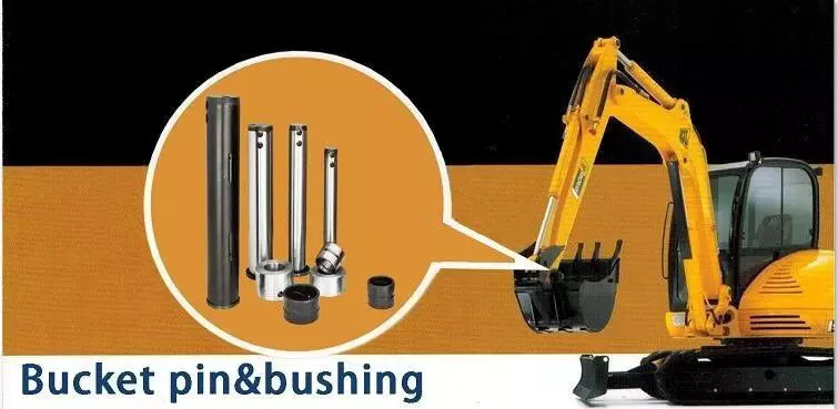
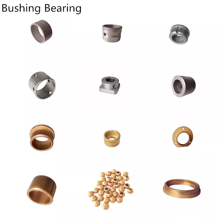
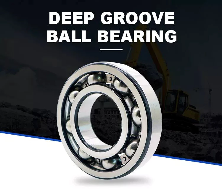
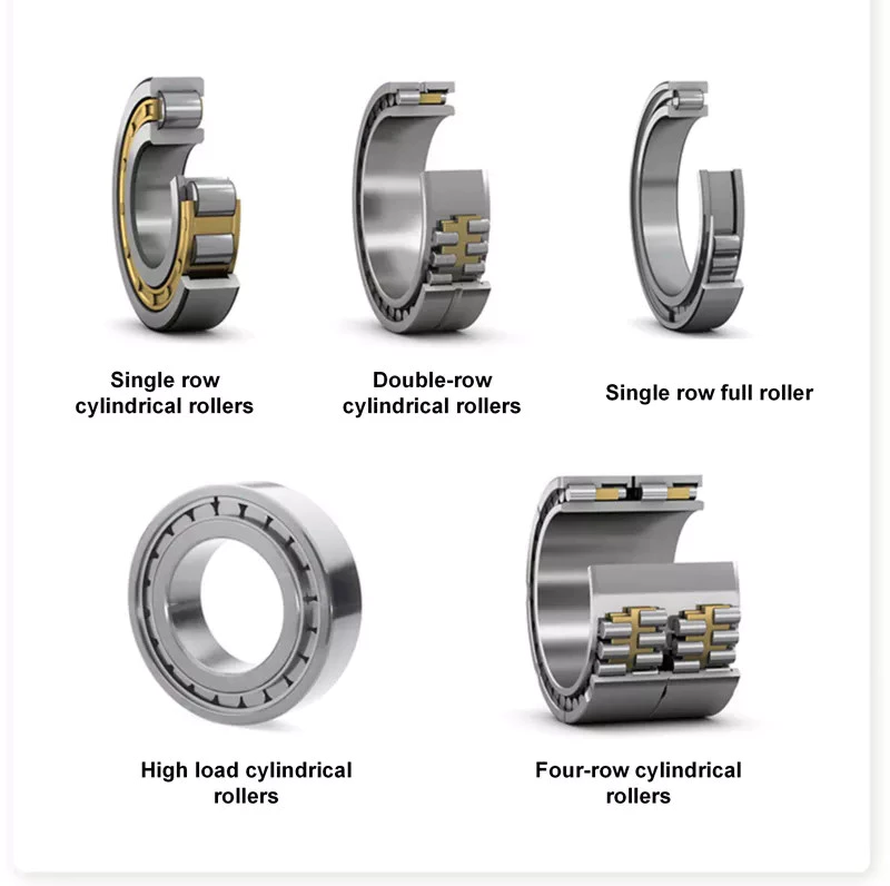
ACCESSORIES EXHIBITION PHOTOS:


One-stop Service
LEO provides one-stop service includes quoting prices, examining goods, arranging delivery, declaring costumes, Clearing costumes, Supporting technology, Offering after-sale services and Expanding service.

LEO FAMILY:

MODEL LIST:
 

All models of pistons that the CZPT brand can produce now :
VG26005711 VG2600030011 VG
612600030034  612600030571/VG1246030001 612600030047/61560030001
612600030017 C4987914 C3917707
1004011-670-0000B 1004011-614-0000B 1004011-630-0000B

BUSINESS FAQ: 

1. How can I become the exclusive agent in this region?

According to the region, the order amount and order quantity need to meet certain requirements. Please contact customer service for specific details.

2. How to perform after-sales service for product quality problems?

Each product provides quality assurance service. If there is a problem with the product within the warranty period, the customer can negotiate with us in detail about the related claims, and we will do our best to satisfy the customer.

3. What is the order process and delivery time?

Submit the list of products you want to buy to us for inquiries. If the price is satisfied, further cooperation will be carried out. The specific cooperation details depend on the specific situation. The normal product preparation period is 3-7 days.
INFINITE FORWARD PLEASURE !


Axle Spindle Types and Installation

Are you looking for a new axle spindle for your vehicle? If so, you’ve come to the right place. Learn more about their types, functions, and installation. After reading this article, you’ll be well on your way to finding your new axle spindle. Axle spindles are essential to your vehicle. There are several types and each has unique characteristics. Here’s how to choose the best 1 for your car.

Dimensions

Axle spindle dimensions are crucial for safe wheel support. This component experiences significant stress and load during bearing mounting and must provide sufficient strength. The axle spindle can be hot-forged or shaped to include an integral shoulder. The shape of the bearing stop region must be abruptly transitioned from a straight to a curved configuration. Dimensions of axle spindle vary with different materials, manufacturing techniques, and applications.
The bearing surfaces of the axle spindle are 1.376 inches across, while the bearing spacer is 1.061 inch across. The axle spindle is 1.376 inches long and includes a cotter pin and nut. Typical axle spindle dimensions are listed below. Some axles may have additional components to reduce their weight, while others may not have any. The number of axles and bearings is also important to consider when determining the dimensions of the axle.
The outside shape of the axle spindle 40 is similar to that of the prior art spindle 10. The outer wheel bearing region 44 is cylindrical with a diameter D 1 and an inner wheel bearing region 46. An axially-separating transition region 48 separates the inner bearing region 46 from the outer wheel bearing region 44. It is important to note that the internal diameter is generally slightly larger than the outer wheel bearing region 46.
Axle spindles can be integrally formed or welded to the housing or central beam. They can also be designed differently depending on the intended function. For example, the trailer axle spindle may have a circular or rectangular cross section. Once again, axle spindles are important for safety and longevity, so it is important to know their dimensions. You can also check online for the dimensions of axle spindles.
Driveshaft

Function

Axle spindles are crucial components of a vehicle’s suspension system. They enable a vehicle to move forward, turn, brake, and accelerate. The axle also supports the wheel bearings. In addition to supporting the wheel hub, the axle spindle connects the arms of each wheel to the chassis. This piece is also known as a steering knuckle. The axle spindle’s job is to provide sufficient strength to support the axle.
The functional elements of an axle spindle are cylindrical and have a transition region and an outer surface with an irregular pattern. They have a first and a second diameter, and are shaped to form the spindle’s beam portion and spindle region. The transition region forms a pivotal connection between the axle and the suspension. It also provides the connection between the axle and the trailer. It allows a vehicle to rotate without causing excessive vibrations.
Axle spindles can be circular in structure and are similar to those of the prior art. They support wheel hub configurations. The first end of a spindle is threaded, while the second end is open. The outer wheel bearing region has an outer surface with a diameter D1, while the inner wheel bearing region 46 has a cylindrical outer surface with a diameter D2. The transition region separates the spindle from the rest of the axle.
The spindle nut retains the wheel hub on the spindle, whereas the spindle nut holds the hub assembly in place. A spindle nut retains the wheel on the spindle. A hub cap protects the locking nut assembly and lubrication area. A hub cap is also a common component of the axle. The hub cap also provides a protective shield for the spindle nut.
Steering axle spindles do not extend to the right of the oil seal. They extend from the steering kunckle, which is pivotally joined to the steering axle beam. Despite the differences in bearing seals, wheel hub mounting means, and brake assemblies, the basic spindle configuration is the same. A spindle consists of 2 axially separated bearing regions, 1 with a larger diameter than the other, with a bearing stop adjacent to the inner bearing region.
Driveshaft

Types

The axle is the basic unit of an automobile, and it includes several components. Among these are bearings, axle housings, and wheel hubs. Bearings and axle housings take on all of the radial loads placed on them during operation. As a result, they are necessary to ensure that a vehicle is able to function at its optimum level. But if you’re not sure what these components are, they can make all the difference in your ride.
Axle type depends on a number of factors, including the amount of force produced. In some cases, the vehicle already has pre-designed axles that come in standard formats, but in other cases, a customer can order a custom-made axle for the specific needs of his vehicle. Customized axles give the vehicle operator greater control over the speed and torque of the wheels. To choose the correct axle type for your vehicle, it’s helpful to know the measurements of the axle.
Axle gear sets and lubrication passages are also different. Reverse-cut gears can’t be used in place of standard cut gears, and vice-versa. The 2 types of axle are compatible, but the spline count of the differential case must match that of the axle. It’s important to remember that a different type of axle may work with a different type of machine tool.
Different axle spindle materials have their own advantages and disadvantages. Some are more durable than others, depending on their load capacity. Disc brake hubs and axle spindles are similar to the non-braking ones, but include a rotor and a caliper yoke. The yoke design on the rotor or caliper spindle is specific for each rotor.
Bearing-type axles are the most durable. They transfer the weight of the vehicle to the axle casing. The axle housing is retained by a flange bolted to the hub, and the axle bearings are secured on the spindle by a large nut. Alternatively, axles with bearings are supported solely on the axle spindle and don’t require a hub. Floating axles are typically better for long-term operation, but may be a limited choice for vehicles.
Driveshaft

Installation

Axle spindle installation involves tightening the axle spindle nut to retain the spacer and bearing cones in position. When properly tightened, the axle spindle nut provides the clamp force required to compress the bearing spacer and bearing cone. Preloading is an important part of axle spindle installation because it optimizes bearing life by limiting the tolerance range of end play. Here are some tips on axle spindle installation.
To start the process, you should remove the axle spindle from the vehicle. If the old spindle is not a bolt-on type, a technician will need to cut the weld that holds the axle spindle in place. Then, he or she would need to thread the new spindle back into place. The axle tube must be threaded to accept the new spindle. Once the axle spindle is properly installed, the technician will need to tighten it to the specified torque.
Once the axle spindle is installed, the technician will continue tightening the nut assembly. To ensure a tight grip, the technician will rotate the outer washer while adjusting the torque level on the axle spindle nut. If the nut is not correctly torqued, it may loosen the axle spindle. In addition, improper torque can cause excessive inboard pressure on the outer nut, which can result in over or under-compression of the bearing cone.
The second axle spindle includes an inboard bearing 54 and an outboard bearing 56. The inboard bearing has an inboard surface that abuts the shoulder 26 of the axle spindle. The outboard bearing 57 is mounted on the axle spindle near its outboard end. A bearing spacer 58 is positioned between the inboard and outboard bearings. The spacer and bearing cone group comprises the bearing cones 54 and 56.
Proper alignment of the new spindle is essential for a secure fit. Taking your trailer to a licensed repair facility for a trailer spindle installation is a good idea, as a poorly installed axle can result in improper wheel tracking and premature tire wear. A licensed trailer repair facility can do this for you without much difficulty. This way, you won’t waste your time or frustration on a DIY trailer axle replacement.

China Hot selling Truck Part Piston Tractor Part Piston for CZPT Shaanxi     with Free Design CustomChina Hot selling Truck Part Piston Tractor Part Piston for CZPT Shaanxi     with Free Design Custom

China Hot selling CZPT Tractor Truck Spare Parts SGS Certification 1017010A29dm Original Truck Oil Filter Assy Oil Filter with Free Design Custom

Product Description

CZPT TRACTOR TRUCK SPARE PARTS Name:
ORIGINAL Truck Oil Filter Assy for CZPT Truck with SGS certification and Competive price(1017571A29DM).

Full Range Spare Parts For China Heavy Duty Trucks with High Quality Best Price.
Spare Parts For : CZPT TRUCK (FAW J5P, CZPT J5M ),  FAW DUMP TRUCK, CZPT TRACTOR TRUCK, CZPT FREIGHT CARRIER TRUCK, MODEL : CZPT J5P, CZPT J6, CZPT J6L, CZPT J6H. CZPT J5M

One Stop Purchasing:
Our Professional Team Has Been Working in Truck Parts and Machinery  Industry for More Than 10 Years, We Cooperate with Different Specialized Factories, To Make Sure We Get the Most Competitive Advantage at Price, and More Important, We could Get the Best OEM Quality.

Packing and Delivery:

Professional Exporting Packing for CZPT Freight, and Air freight.

Product Name: Heavy Duty Truck Parts
Brand : FAW/HOWO/ Shacman/ Sinotruk/ZheJiang / Foton/ Auman/ Northbenz/ Beiben
Quality: Top Class
Packing: Standard Packing
Leading Time: 15 days-30 days For Bulk orders
Small Delivery: 3 days
Payment term: 30% of Invoice amount by T/T as Deposit, balance before shipment. L/C is acceptable if the order amount is more than US$500,000
Fit for Truck  Model: FAW J5P, CZPT J5M,, CZPT J6


We care about customers’ concerns, we are strong in assisting and cooperating with Construction companies, Transportation logistics companies, and road and bridge building companies, as you don’t have to spend a lot of time and effort on finding out the part numbers, we can do it for you with the VIN numbers of your equipments, we do this as well to reduce the possibility of wrong parts delivery. And for the urgent needs, our superior logistic can make sure that you could get the parts in 3-4 days in most cases.

 WE PROVIDE POWER TO THE MACHINES WORKING ON THE LAND.

Driveshaft structure and vibrations associated with it

The structure of the drive shaft is critical to its efficiency and reliability. Drive shafts typically contain claw couplings, rag joints and universal joints. Other drive shafts have prismatic or splined joints. Learn about the different types of drive shafts and how they work. If you want to know the vibrations associated with them, read on. But first, let’s define what a driveshaft is.
air-compressor

transmission shaft

As the demand on our vehicles continues to increase, so does the demand on our drive systems. Higher CO2 emission standards and stricter emission standards increase the stress on the drive system while improving comfort and shortening the turning radius. These and other negative effects can place significant stress and wear on components, which can lead to driveshaft failure and increase vehicle safety risks. Therefore, the drive shaft must be inspected and replaced regularly.
Depending on your model, you may only need to replace 1 driveshaft. However, the cost to replace both driveshafts ranges from $650 to $1850. Additionally, you may incur labor costs ranging from $140 to $250. The labor price will depend on your car model and its drivetrain type. In general, however, the cost of replacing a driveshaft ranges from $470 to $1850.
Regionally, the automotive driveshaft market can be divided into 4 major markets: North America, Europe, Asia Pacific, and Rest of the World. North America is expected to dominate the market, while Europe and Asia Pacific are expected to grow the fastest. Furthermore, the market is expected to grow at the highest rate in the future, driven by economic growth in the Asia Pacific region. Furthermore, most of the vehicles sold globally are produced in these regions.
The most important feature of the driveshaft is to transfer the power of the engine to useful work. Drive shafts are also known as propeller shafts and cardan shafts. In a vehicle, a propshaft transfers torque from the engine, transmission, and differential to the front or rear wheels, or both. Due to the complexity of driveshaft assemblies, they are critical to vehicle safety. In addition to transmitting torque from the engine, they must also compensate for deflection, angular changes and length changes.

type

Different types of drive shafts include helical shafts, gear shafts, worm shafts, planetary shafts and synchronous shafts. Radial protruding pins on the head provide a rotationally secure connection. At least 1 bearing has a groove extending along its circumferential length that allows the pin to pass through the bearing. There can also be 2 flanges on each end of the shaft. Depending on the application, the shaft can be installed in the most convenient location to function.
Propeller shafts are usually made of high-quality steel with high specific strength and modulus. However, they can also be made from advanced composite materials such as carbon fiber, Kevlar and fiberglass. Another type of propeller shaft is made of thermoplastic polyamide, which is stiff and has a high strength-to-weight ratio. Both drive shafts and screw shafts are used to drive cars, ships and motorcycles.
Sliding and tubular yokes are common components of drive shafts. By design, their angles must be equal or intersect to provide the correct angle of operation. Unless the working angles are equal, the shaft vibrates twice per revolution, causing torsional vibrations. The best way to avoid this is to make sure the 2 yokes are properly aligned. Crucially, these components have the same working angle to ensure smooth power flow.
The type of drive shaft varies according to the type of motor. Some are geared, while others are non-geared. In some cases, the drive shaft is fixed and the motor can rotate and steer. Alternatively, a flexible shaft can be used to control the speed and direction of the drive. In some applications where linear power transmission is not possible, flexible shafts are a useful option. For example, flexible shafts can be used in portable devices.
air-compressor

put up

The construction of the drive shaft has many advantages over bare metal. A shaft that is flexible in multiple directions is easier to maintain than a shaft that is rigid in other directions. The shaft body and coupling flange can be made of different materials, and the flange can be made of a different material than the main shaft body. For example, the coupling flange can be made of steel. The main shaft body is preferably flared on at least 1 end, and the at least 1 coupling flange includes a first generally frustoconical projection extending into the flared end of the main shaft body.
The normal stiffness of fiber-based shafts is achieved by the orientation of parallel fibers along the length of the shaft. However, the bending stiffness of this shaft is reduced due to the change in fiber orientation. Since the fibers continue to travel in the same direction from the first end to the second end, the reinforcement that increases the torsional stiffness of the shaft is not affected. In contrast, a fiber-based shaft is also flexible because it uses ribs that are approximately 90 degrees from the centerline of the shaft.
In addition to the helical ribs, the drive shaft 100 may also contain reinforcing elements. These reinforcing elements maintain the structural integrity of the shaft. These reinforcing elements are called helical ribs. They have ribs on both the outer and inner surfaces. This is to prevent shaft breakage. These elements can also be shaped to be flexible enough to accommodate some of the forces generated by the drive. Shafts can be designed using these methods and made into worm-like drive shafts.

vibration

The most common cause of drive shaft vibration is improper installation. There are 5 common types of driveshaft vibration, each related to installation parameters. To prevent this from happening, you should understand what causes these vibrations and how to fix them. The most common types of vibration are listed below. This article describes some common drive shaft vibration solutions. It may also be beneficial to consider the advice of a professional vibration technician for drive shaft vibration control.
If you’re not sure if the problem is the driveshaft or the engine, try turning on the stereo. Thicker carpet kits can also mask vibrations. Nonetheless, you should contact an expert as soon as possible. If vibration persists after vibration-related repairs, the driveshaft needs to be replaced. If the driveshaft is still under warranty, you can repair it yourself.
CV joints are the most common cause of third-order driveshaft vibration. If they are binding or fail, they need to be replaced. Alternatively, your CV joints may just be misaligned. If it is loose, you can check the CV connector. Another common cause of drive shaft vibration is improper assembly. Improper alignment of the yokes on both ends of the shaft can cause them to vibrate.
Incorrect trim height can also cause driveshaft vibration. Correct trim height is necessary to prevent drive shaft wobble. Whether your vehicle is new or old, you can perform some basic fixes to minimize problems. One of these solutions involves balancing the drive shaft. First, use the hose clamps to attach the weights to it. Next, attach an ounce of weight to it and spin it. By doing this, you minimize the frequency of vibration.
air-compressor

cost

The global driveshaft market is expected to exceed (xxx) million USD by 2028, growing at a compound annual growth rate (CAGR) of XX%. Its soaring growth can be attributed to several factors, including increasing urbanization and R&D investments by leading market players. The report also includes an in-depth analysis of key market trends and their impact on the industry. Additionally, the report provides a comprehensive regional analysis of the Driveshaft Market.
The cost of replacing the drive shaft depends on the type of repair required and the cause of the failure. Typical repair costs range from $300 to $750. Rear-wheel drive cars usually cost more. But front-wheel drive vehicles cost less than four-wheel drive vehicles. You may also choose to try repairing the driveshaft yourself. However, it is important to do your research and make sure you have the necessary tools and equipment to perform the job properly.
The report also covers the competitive landscape of the Drive Shafts market. It includes graphical representations, detailed statistics, management policies, and governance components. Additionally, it includes a detailed cost analysis. Additionally, the report presents views on the COVID-19 market and future trends. The report also provides valuable information to help you decide how to compete in your industry. When you buy a report like this, you are adding credibility to your work.
A quality driveshaft can improve your game by ensuring distance from the tee and improving responsiveness. The new material in the shaft construction is lighter, stronger and more responsive than ever before, so it is becoming a key part of the driver. And there are a variety of options to suit any budget. The main factor to consider when buying a shaft is its quality. However, it’s important to note that quality doesn’t come cheap and you should always choose an axle based on what your budget can handle.

China Hot selling CZPT Tractor Truck Spare Parts SGS Certification 1017010A29dm Original Truck Oil Filter Assy Oil Filter     with Free Design CustomChina Hot selling CZPT Tractor Truck Spare Parts SGS Certification 1017010A29dm Original Truck Oil Filter Assy Oil Filter     with Free Design Custom

China Best Sales Heavy Truck Trailer Parts Widely Application Square Axle 13ton 16ton Trailer Axle for Semi Trailer Parts Semi Trailer Tractor Truck German Axle near me shop

Product Description

Recommended Spring Seat
FB(mm) C/D/∅(mm)
75 100/180/24
90 115/180/27
100 125/180/27

Axle Type Max Capacity
(kg)
Brake Size
(mm)
Track
TR(mm)
Spring Seat
LM(mm)
Axle Beam
(mm)
GM
(mm)
Wheel Fixing Total Length
LP(mm)
Weight
(kg)
Bearing
Studs P.C.D. ∅H(mm)
ZI12GA-1 12,000 420×180 1820 ≤435 127 402 10-M22x1.5 ISO 335 281 2135 335 33213  33118
ZI12GA-2 12,000 420×180 1840 ≤455 150 422 10-M22x1.5 ISO 335 281 2155 360 33213  33118
ZI12GA-3 12,000 420×200 1840 ≤455 150 354 10-M22x1.5 ISO 335 281 2155 373 33213  33118
ZI12GA-4 12,000 420×180 2040 ≤455 150 622 8xM20X1.5 JIS 285.75 281 2355 375 33213  33118
ZI12GA-5 14,000 420×200 1840 ≤455 150 354 10-M22x1.5 ISO 335 281 2185 410 33215  32219
ZI12GA-6 14,000 420×220 1840 ≤455 150 354 10-M22x1.5 ISO 335 281 2185 415 33215  32219
ZI12GA-7 16,000 420×200 1850 ≤455 150 356 10-M22x1.5 ISO 335 281 2240 442 32314  32222
ZI12GA-8 16,000 420×220 1850 ≤455 150 376 10-M22x1.5 ISO 335 281 2240 455 32314  32222
ZI12GA-9 18,000 420×220 1850 ≤455 150 376 10-M22x1.5 ISO 335 281 2240 475 32314  32222


The Benefits of Spline Couplings for Disc Brake Mounting Interfaces

Spline couplings are commonly used for securing disc brake mounting interfaces. Spline couplings are often used in high-performance vehicles, aeronautics, and many other applications. However, the mechanical benefits of splines are not immediately obvious. Listed below are the benefits of spline couplings. We’ll discuss what these advantages mean for you. Read on to discover how these couplings work.

Disc brake mounting interfaces are splined

There are 2 common disc brake mounting interfaces – splined and six-bolt. Splined rotors fit on splined hubs; six-bolt rotors will need an adapter to fit on six-bolt hubs. The six-bolt method is easier to maintain and may be preferred by many cyclists. If you’re thinking of installing a disc brake system, it is important to know how to choose the right splined and center lock interfaces.
splineshaft

Aerospace applications

The splines used for spline coupling in aircraft are highly complex. While some previous researches have addressed the design of splines, few publications have tackled the problem of misaligned spline coupling. Nevertheless, the accurate results we obtained were obtained using dedicated simulation tools, which are not commercially available. Nevertheless, such tools can provide a useful reference for our approach. It would be beneficial if designers could use simple tools for evaluating contact pressure peaks. Our analytical approach makes it possible to find answers to such questions.
The design of a spline coupling for aerospace applications must be accurate to minimize weight and prevent failure mechanisms. In addition to weight reduction, it is necessary to minimize fretting fatigue. The pressure distribution on the spline coupling teeth is a significant factor in determining its fretting fatigue. Therefore, we use analytical and experimental methods to examine the contact pressure distribution in the axial direction of spline couplings.
The teeth of a spline coupling can be categorized by the type of engagement they provide. This study investigates the position of resultant contact forces in the teeth of a spline coupling when applied to pitch diameter. Using FEM models, numerical results are generated for nominal and parallel offset misalignments. The axial tooth profile determines the behavior of the coupling component and its ability to resist wear. Angular misalignment is also a concern, causing misalignment.
In order to assess wear damage of a spline coupling, we must take into consideration the impact of fretting on the components. This wear is caused by relative motion between the teeth that engage them. The misalignment may be caused by vibrations, cyclical tooth deflection, or angular misalignment. The result of this analysis may help designers improve their spline coupling designs and develop improved performance.
CZPT polyimide, an abrasion-resistant polymer, is a popular choice for high-temperature spline couplings. This material reduces friction and wear, provides a low friction surface, and has a low wear rate. Furthermore, it offers up to 50 times the life of metal on metal spline connections. For these reasons, it is important to choose the right material for your spline coupling.
splineshaft

High-performance vehicles

A spline coupler is a device used to connect splined shafts. A typical spline coupler resembles a short pipe with splines on either end. There are 2 basic types of spline coupling: single and dual spline. One type attaches to a drive shaft, while the other attaches to the gearbox. While spline couplings are typically used in racing, they’re also used for performance problems.
The key challenge in spline couplings is to determine the optimal dimension of spline joints. This is difficult because no commercial codes allow the simulation of misaligned joints, which can destroy components. This article presents analytical approaches to estimating contact pressures in spline connections. The results are comparable with numerical approaches but require special codes to accurately model the coupling operation. This research highlights several important issues and aims to make the application of spline couplings in high-performance vehicles easier.
The stiffness of spline assemblies can be calculated using tooth-like structures. Such splines can be incorporated into the spline joint to produce global stiffness for torsional vibration analysis. Bearing reactions are calculated for a certain level of misalignment. This information can be used to design bearing dimensions and correct misalignment. There are 3 types of spline couplings.
Major diameter fit splines are made with tightly controlled outside diameters. This close fit provides concentricity transfer from the male to the female spline. The teeth of the male spline usually have chamfered tips and clearance with fillet radii. These splines are often manufactured from billet steel or aluminum. These materials are renowned for their strength and uniform grain created by the forging process. ANSI and DIN design manuals define classes of fit.
splineshaft

Disc brake mounting interfaces

A spline coupling for disc brake mounting interfaces is a type of hub-to-brake-disc mount. It is a highly durable coupling mechanism that reduces heat transfer from the disc to the axle hub. The mounting arrangement also isolates the axle hub from direct contact with the disc. It is also designed to minimize the amount of vehicle downtime and maintenance required to maintain proper alignment.
Disc brakes typically have substantial metal-to-metal contact with axle hub splines. The discs are held in place on the hub by intermediate inserts. This metal-to-metal contact also aids in the transfer of brake heat from the brake disc to the axle hub. Spline coupling for disc brake mounting interfaces comprises a mounting ring that is either a threaded or non-threaded spline.
During drag brake experiments, perforated friction blocks filled with various additive materials are introduced. The materials included include Cu-based powder metallurgy material, a composite material, and a Mn-Cu damping alloy. The filling material affects the braking interface’s wear behavior and friction-induced vibration characteristics. Different filling materials produce different types of wear debris and have different wear evolutions. They also differ in their surface morphology.
Disc brake couplings are usually made of 2 different types. The plain and HD versions are interchangeable. The plain version is the simplest to install, while the HD version has multiple components. The two-piece couplings are often installed at the same time, but with different mounting interfaces. You should make sure to purchase the appropriate coupling for your vehicle. These interfaces are a vital component of your vehicle and must be installed correctly for proper operation.
Disc brakes use disc-to-hub elements that help locate the forces and displace them to the rim. These elements are typically made of stainless steel, which increases the cost of manufacturing the disc brake mounting interface. Despite their benefits, however, the high braking force loads they endure are hard on the materials. Moreover, excessive heat transferred to the intermediate elements can adversely affect the fatigue life and long-term strength of the brake system.

China Best Sales Heavy Truck Trailer Parts Widely Application Square Axle 13ton 16ton Trailer Axle for Semi Trailer Parts Semi Trailer Tractor Truck German Axle     near me shop China Best Sales Heavy Truck Trailer Parts Widely Application Square Axle 13ton 16ton Trailer Axle for Semi Trailer Parts Semi Trailer Tractor Truck German Axle     near me shop

China Custom Wholesale Price 44310-2200 H07D Auto Parts Hydraulic Power Steering Pump for Hino Bus Tractor Truck Parts near me manufacturer

Product Description


GREEN Hydraulic
 is 1 strength Professional enterprise which integrates in Hydraulic Component with more than 15 years experience focusing on the abroad and Domestic Market. Our products including Piston Pump, Vane Pump, Gear Pump, Hydraulic Valve, Hydraulic Motor, Electric Motor, Oil Cooler, Accumulator and other hydraulic accessories etc. GREEN Hydraulic Piston Pump Series including CY, A2F, A2FO, A7V, A4V, A10V Series, which is the same as Orignal Rexroth, the same appreance, mounting size and working perofrmance. The products are widely used in machine tool, forging machinery, metallurgy machinery, engineering machinery, mine machinery and other hydraulic systems. They also can be used as hydraulic motors if the valve plate is changed into motor type. GREEN also supply replacement parts for Komatsu, Rexroth, Sauer, Hitachi, Catpillar, KYB, Kawasaki, Toshiba, Linde, Vickers, Yuekn, Nachi…Please consult online customer service for more models

The Benefits of Using Self-Lubricating Bushings for Your Next Pivot

Like any other auto part, control arm bushings wear out over time. This results in an increase in irritating vibrations that can be dangerous in severe cases. The bushings in the control arms also wear out due to the stress that extreme driving conditions put on the control arms. Additionally, environmental factors and oversized tires tend to transmit more vibration through the bushing than conventionally sized tires. Whatever the cause, bushings can be the source of many problems.
bushing

wear and cracking

The main cause of dry valve side bushing cracking is a mismatch in thermal expansion of the core and flange. This situation can seriously compromise the safety of the power system. To improve the safety of dry valve side bushings, the crack development of epoxy impregnated paper under various conditions was investigated. A coupled thermomechanical simulation model was also used to study the cracking process.
The first step in diagnosing the cause of bushing wear and cracking is a visual inspection. The bushing of the lower control arm is fixed to the frame by a bracket. If there are any visible cracks, it’s time to replace the bushing. However, there is no need to replace the entire suspension. In some cases, worn bushings can cause a variety of problems, including body lean, excessive tire wear and cornering noise.

Maintenance free

If you’re considering maintenance-free bushings for your next pivot, you’ll be wondering what to look for in these components. The bushing protects the housing from corrosion and keeps the bushing under pressure. However, many users are not familiar with what these components can do for their applications. In this article, we’ll look at several examples of truly maintenance-free pivots and discuss their requirements.
One of the most popular types of maintenance-free bushings are flanged and parallel. Unlike worm gear bushings, these self-lubricating metal bearings are ideal for a variety of applications and conditions. They reduce failure and downtime costs while providing the long-term lubrication required by other types of bushings. Since these sleeves are made of lead-free material, they are RoHS compliant, which means they are environmentally friendly.Another common maintenance-free bushing is plastic. This material is easier to find off-the-shelf and relatively inexpensive to produce. However, it is not suitable for high load applications as it will crack under heavy loads and damage mating parts. Plastics can also deviate if the manufacturing process is imprecise. Plastic bushings can also crack when subjected to high loads.
bushing

self-lubricating

When using a self-lubricating bushing, there is no need to apply grease to the bushing. Oily liquids tend to attract dirt and grit, which can wear away the graphite prematurely. By eliminating the need for regular lubrication, you will reduce equipment maintenance costs. This article will explore the benefits of self-lubricating bushings. You will love your kindness.
Self-lubricating bushings have a strong base material to withstand radial bearing pressure while providing shaft support at the contact surfaces. The material also has good fatigue properties and low friction motion. Self-lubricating bushings can be used in environments with high temperatures and aggressive media. These products can also withstand enormous pressure. When using self-lubricating bushings, it is important to select the correct material.
The main advantage of using self-lubricating bushings is ease of maintenance. They don’t require oil to run and are cheaper to buy. Their main benefit is that they can significantly reduce your machine running costs. These bearings do not require oiling operations, reducing maintenance costs. These bearings also offer a simplified mechanical design due to their thin walls and high load capacity. In addition, they reduce noise levels while maintaining excellent wear resistance. Plus, their materials are ROHS compliant, which means they don’t require oil.
Hydropower installations are another area where self-lubricating bushings have proven their advantages. They reduce maintenance costs, extend equipment life, and improve environmental benefits. For example, the Newfoundland Power Company uses self-lubricating bushings in the gates of its hydroelectric power plants. These self-lubricating bushings eliminate grease from entering waterways and tailraces. As a result, power companies are able to reduce maintenance and costs.

compared to cartilage in the human body

What is the difference between tendon, bone and cartilage? Human cartilage is composed of collagen and elastic fibers. In contrast, fibrocartilage contains more collagen than hyaline cartilage. Both cartilage types are composed of proteoglycans, which have a protein backbone and glycosaminoglycan side chains. These components work together to provide structure and flexibility to the cartilage.
Bone is a combination of living and dead cells embedded in a matrix. The outer hard layer of bone is dense bone, and the inner layer is spongy, containing bone marrow, blood vessels, nerves, etc. Bone contains both organic and inorganic substances, and this process of hardening of the matrix produces bone. On the other hand, cartilage consists of chondrocytes and a matrix composed of collagen and elastin fibers. Compared to bone, cartilage is yellow and contains elastic fibers.
Although bone and cartilage are structurally identical, cartilage is more flexible. It is mainly found in the joints and respiratory system and requires flexibility. Its ingredients include collagen and proteoglycans, which provide compression and abrasion resistance. Furthermore, connective tissue is composed of cells, fibers and matrix.
The basic substance of cartilage is chondroitin sulfate, which is derived from animals. Although cartilage grows more slowly than bone, its microstructure is less organized. There is a fibrous sheath covering the cartilage, called the perichondrium. The molecular composition of the ECM plays an important role in the function of cartilage. The collagen matrix is ​​important for cartilage remodeling and consists of changes in the collagen matrix.
bushing

Compared to metal-on-bone contact

Both metal-on-bone contact are known to cause a significant increase in the pressures in a joint. To compare the two, we first calculated the joint contact pressures in each model and compared them. The results of this study support previous research on this subject. The following sections discuss the benefits of both types of contact. They also outline some key differences between the two.

China Custom Wholesale Price 44310-2200 H07D Auto Parts Hydraulic Power Steering Pump for Hino Bus Tractor Truck Parts     near me manufacturer China Custom Wholesale Price 44310-2200 H07D Auto Parts Hydraulic Power Steering Pump for Hino Bus Tractor Truck Parts     near me manufacturer

China Professional Good Price 7673 955 804 303 Eicher 34071539001 Auto Parts Hydraulic Power Steering Pump Tata for Tractor Truck Parts near me manufacturer

Product Description


GREEN Hydraulic
 is 1 strength Professional enterprise which integrates in Hydraulic Component with more than 15 years experience focusing on the abroad and Domestic Market. Our products including Piston Pump, Vane Pump, Gear Pump, Hydraulic Valve, Hydraulic Motor, Electric Motor, Oil Cooler, Accumulator and other hydraulic accessories etc. GREEN Hydraulic Piston Pump Series including CY, A2F, A2FO, A7V, A4V, A10V Series, which is the same as Orignal Rexroth, the same appreance, mounting size and working perofrmance. The products are widely used in machine tool, forging machinery, metallurgy machinery, engineering machinery, mine machinery and other hydraulic systems. They also can be used as hydraulic motors if the valve plate is changed into motor type. GREEN also supply replacement parts for Komatsu, Rexroth, Sauer, Hitachi, Catpillar, KYB, Kawasaki, Toshiba, Linde, Vickers, Yuekn, Nachi…Please consult online customer service for more models

Types of Screw Shafts

Screw shafts come in various types and sizes. These types include fully threaded, Lead, and Acme screws. Let’s explore these types in more detail. What type of screw shaft do you need? Which 1 is the best choice for your project? Here are some tips to choose the right screw:

Machined screw shaft

The screw shaft is a basic piece of machinery, but it can be further customized depending on the needs of the customer. Its features include high-precision threads and ridges. Machined screw shafts are generally manufactured using high-precision CNC machines or lathes. The types of screw shafts available vary in shape, size, and material. Different materials are suitable for different applications. This article will provide you with some examples of different types of screw shafts.
Ball screws are used for a variety of applications, including mounting machines, liquid crystal devices, measuring devices, and food and medical equipment. Various shapes are available, including miniature ball screws and nut brackets. They are also available without keyway. These components form a high-accuracy feed mechanism. Machined screw shafts are also available with various types of threaded ends for ease of assembly. The screw shaft is an integral part of linear motion systems.
When you need a machined screw shaft, you need to know the size of the threads. For smaller machine screws, you will need a mating part. For smaller screw sizes, the numbers will be denominated as industry Numeric Sizes. These denominations are not metric, but rather in mm, and they may not have a threads-per-inch designation. Similarly, larger machine screws will usually have threads that have a higher pitch than those with a lower pitch.
Another important feature of machine screws is that they have a thread on the entire shaft, unlike their normal counterparts. These machine screws have finer threads and are intended to be screwed into existing tapped holes using a nut. This means that these screws are generally stronger than other fasteners. They are usually used to hold together electronic components, industrial equipment, and engines. In addition to this, machine screws are usually made of a variety of materials.
screwshaft

Acme screw

An Acme screw is the most common type of threaded shaft available. It is available in a variety of materials including stainless steel and carbon steel. In many applications, it is used for large plates in crushing processes. ACME screws are self-locking and are ideal for applications requiring high clamping force and low friction. They also feature a variety of standard thread forms, including knurling and rolled worms.
Acme screws are available in a wide range of sizes, from 1/8″ to 6″. The diameter is measured from the outside of the screw to the bottom of the thread. The pitch is equal to the lead in a single start screw. The lead is equal to the pitch plus the number of starts. A screw of either type has a standard pitch and a lead. Acme screws are manufactured to be accurate and durable. They are also widely available in a wide range of materials and can be customized to fit your needs.
Another type of Acme screw is the ball screw. These have no back drive and are widely used in many applications. Aside from being lightweight, they are also able to move at faster speeds. A ball screw is similar to an Acme screw, but has a different shape. A ball screw is usually longer than an Acme screw. The ball screw is used for applications that require high linear speeds. An Acme screw is a common choice for many industries.
There are many factors that affect the speed and resolution of linear motion systems. For example, the nut position and the distance the screw travels can all affect the resolution. The total length of travel, the speed, and the duty cycle are all important. The lead size will affect the maximum linear speed and force output. If the screw is long, the greater the lead size, the higher the resolution. If the lead length is short, this may not be the most efficient option.
screwshaft

Lead screw

A lead screw is a threaded mechanical device. A lead screw consists of a cylindrical shaft, which includes a shallow thread portion and a tightly wound spring wire. This spring wire forms smooth, hard-spaced thread convolutions and provides wear-resistant engagement with the nut member. The wire’s leading and trailing ends are anchored to the shaft by means appropriate to the shaft’s composition. The screw is preferably made of stainless steel.
When selecting a lead screw, 1 should first determine its critical speed. The critical speed is the maximum rotations per minute based on the natural frequency of the screw. Excessive backlash will damage the lead screw. The maximum number of revolutions per minute depends on the screw’s minor diameter, length, assembly alignment, and end fixity. Ideally, the critical speed is 80% of its evaluated critical speed. A critical speed is not exceeded because excessive backlash would damage the lead screw and may be detrimental to the screw’s performance.
The PV curve defines the safe operating limits of a lead screw. This relationship describes the inverse relationship between contact surface pressure and sliding velocity. As the PV value increases, a lower rotation speed is required for heavier axial loads. Moreover, PV is affected by material and lubrication conditions. Besides, end fixity, which refers to the way the lead screw is supported, also affects its critical speed. Fixed-fixed and free end fixity are both possible.
Lead screws are widely used in industries and everyday appliances. In fact, they are used in robotics, lifting equipment, and industrial machinery. High-precision lead screws are widely used in the fields of engraving, fluid handling, data storage, and rapid prototyping. Moreover, they are also used in 3D printing and rapid prototyping. Lastly, lead screws are used in a wide range of applications, from measuring to assembly.

Fully threaded screw

A fully threaded screw shaft can be found in many applications. Threading is an important feature of screw systems and components. Screws with threaded shafts are often used to fix pieces of machinery together. Having fully threaded screw shafts ensures that screws can be installed without removing the nut or shaft. There are 2 major types of screw threads: coarse and fine. When it comes to coarse threads, UTS is the most common type, followed by BSP.
In the 1840s, a British engineer named Joseph Whitworth created a design that was widely used for screw threads. This design later became the British Standard Whitworth. This standard was used for screw threads in the United States during the 1840s and 1860s. But as screw threads evolved and international standards were established, this system remained largely unaltered. A new design proposed in 1864 by William Sellers improved upon Whitworth’s screw threads and simplified the pitch and surface finish.
Another reason for using fully threaded screws is their ability to reduce heat. When screw shafts are partially threaded, the bone grows up to the screw shaft and causes the cavity to be too narrow to remove it. Consequently, the screw is not capable of backing out. Therefore, fully threaded screws are the preferred choice for inter-fragmentary compression in children’s fractures. However, surgeons should know the potential complication when removing metalwork.
The full thread depth of a fully threaded screw is the distance at which a male thread can freely thread into the shaft. This dimension is typically 1 millimeter shy of the total depth of the drilled hole. This provides space for tap lead and chips. The full-thread depth also makes fully threaded screws ideal for axially-loaded connections. It is also suitable for retrofitting applications. For example, fully threaded screws are commonly used to connect 2 elements.
screwshaft

Ball screw

The basic static load rating of a ball screw is determined by the product of the maximum axial static load and the safety factor “s0”. This factor is determined by past experience in similar applications and should be selected according to the design requirements of the application. The basic static load rating is a good guideline for selecting a ball screw. There are several advantages to using a ball screw for a particular application. The following are some of the most common factors to consider when selecting a ball screw.
The critical speed limit of a ball screw is dependent on several factors. First of all, the critical speed depends on the mass, length and diameter of the shaft. Second, the deflection of the shaft and the type of end bearings determine the critical speed. Finally, the unsupported length is determined by the distance between the ball nut and end screw, which is also the distance between bearings. Generally, a ball screw with a diameter greater than 1.2 mm has a critical speed limit of 200 rpm.
The first step in manufacturing a high-quality ball screw is the choice of the right steel. While the steel used for manufacturing a ball screw has many advantages, its inherent quality is often compromised by microscopic inclusions. These microscopic inclusions may eventually lead to crack propagation, surface fatigue, and other problems. Fortunately, the technology used in steel production has advanced, making it possible to reduce the inclusion size to a minimum. However, higher-quality steels can be expensive. The best material for a ball screw is vacuum-degassed pure alloy steel.
The lead of a ball screw shaft is also an important factor to consider. The lead is the linear distance between the ball and the screw shaft. The lead can increase the amount of space between the balls and the screws. In turn, the lead increases the speed of a screw. If the lead of a ball screw is increased, it may increase its accuracy. If not, the lead of a ball screw can be improved through preloading, lubrication, and better mounting accuracy.

China Professional Good Price 7673 955 804 303 Eicher 34071539001 Auto Parts Hydraulic Power Steering Pump Tata for Tractor Truck Parts     near me manufacturer China Professional Good Price 7673 955 804 303 Eicher 34071539001 Auto Parts Hydraulic Power Steering Pump Tata for Tractor Truck Parts     near me manufacturer

China supplier Trade Assurance 7685 955 180 81.47101.6137 7685955180 Auto Parts Hydraulic Power Steering Pump for Man Bus Tractor Truck Parts wholesaler

Product Description


GREEN Hydraulic
 is 1 strength Professional enterprise which integrates in Hydraulic Component with more than 15 years experience focusing on the abroad and Domestic Market. Our products including Piston Pump, Vane Pump, Gear Pump, Hydraulic Valve, Hydraulic Motor, Electric Motor, Oil Cooler, Accumulator and other hydraulic accessories etc. GREEN Hydraulic Piston Pump Series including CY, A2F, A2FO, A7V, A4V, A10V Series, which is the same as Orignal Rexroth, the same appreance, mounting size and working perofrmance. The products are widely used in machine tool, forging machinery, metallurgy machinery, engineering machinery, mine machinery and other hydraulic systems. They also can be used as hydraulic motors if the valve plate is changed into motor type. GREEN also supply replacement parts for Komatsu, Rexroth, Sauer, Hitachi, Catpillar, KYB, Kawasaki, Toshiba, Linde, Vickers, Yuekn, Nachi…Please consult online customer service for more models

Types of Ball Bearings

Modern ball bearing configurations have different materials and geometries to meet the demands of different working environments and applications. There are different types of ball bearings: single row deep groove, double-row deep groove, angular contact ball bearing, thrust, and self-aligning. Let us look at the differences between each type and learn why they are important for various purposes. Listed below are some of the most common types of ball bearings.

Miniature bearings

Although miniature ball bearings are a popular choice for small mechanical components, they are not without their challenges. They must be properly lubricated and stored in clean rooms. A strand of hair could ruin a miniature bearing. Fortunately, manufacturers offer lubrication services and a “Clean Room” for customers to store their miniature bearings safely. Read on to learn more about these small bearings and how they can help you.
The size of a miniature ball bearing can vary significantly, but most types of these devices are available in sizes ranging from.040 inch to 1 eighth of an inch. Whether you need a small ball bearing for a miniature car or a tiny instrument, a miniature bearing can save space while still offering high performance. Many of these bearings are shielded to prevent dirt from entering and leakage of lubricant. They can be flanged or unflanged, and some miniature ball bearings have extended inner rings that are designed for easy plate mounting.
Miniature ball bearings are commonly made from stainless steel or chrome steel. Both metals have their advantages. Stainless steel is the most popular material for ball bearings, which allows for a high load capacity while being quiet. Because stainless steel is relatively inexpensive, many small instrument bearings are made entirely of stainless steel. The difference in price is minimal, as the amount of steel is relatively small. Stainless steel miniature bearings are the smallest and lightest of all types of miniature ball bearings.

Self-aligning ball bearings

bearing
In the simplest terms, self-aligning ball bearings are ball bearings with flex shafts. If you’re looking for a ball bearing with a high degree of precision, you’ll want to choose 1 with a flex shaft, which means it can adjust to the proper orientation of the bearing’s flex shaft. Ball bearings with flex shafts are also recommended. But, what are these bearings?
Self-aligning ball bearings are made with 2 rows of balls and a common sphered raceway on the outer ring. As a result, they can accommodate small errors in shaft alignment and mounting. The CZPT brand is especially suitable for high-speed applications requiring greater running accuracy. The self-alignment mechanism is enabled by the fact that the balls are placed in 2 rows on either side of the sphered raceway in the outer ring. These 2 rows of balls also promote reduced friction and wear.
Another type of self-aligning ball bearings is a double-row design. They feature a common sphered raceway on the outer ring, a hollow spherical ring, and a cage that rotates relative to it. A self-aligning ball bearing is used in applications where shaft misalignment is a problem, such as conveying equipment. They are also used in simple woodworking machinery and ventilators.

Ceramic ball bearings

Ceramic ball bearings have several advantages over steel or metal bearings. These include increased acceleration capability, reduced friction, improved wear-resistance, and higher speeds. The United States holds the leading position in the global ceramic ball bearings market thanks to a rebounding motor vehicle production and healthy fixed investment environment. In the United States, there are 3 primary markets for ceramic ball bearings: healthcare, automotive, and aerospace. Here are the main benefits of ceramic ball bearings:
Hybrid ball bearings are also available. Hybrid bearings feature traditional metal rings and silicon nitride (ceramic) balls. Hybrid bearings offer important performance advantages over all-steel bearings, and they are more affordable. However, full ceramic ball bearings have all ceramic parts, and are best suited for machines that require high precision. These types of bearings also resist corrosion and wear.
Compared to steel ball bearings, ceramic balls are lighter than steel. They are also less dense, which means less friction and therefore less heat. Additionally, ceramic balls operate at higher speeds than steel balls, which increases their durability and longevity. But they are still not as strong as steel bearings. And because of their reduced density, they are much cheaper to manufacture. Therefore, they are an excellent choice for many applications. You can expect them to last much longer than steel bearings.

Steel carbon ball bearings

High precision G25 ball bearings are made of the highest grade chrome steel and hot forged from bar stock. Statistical process control and exacting atmospheres help ensure uniform hardness and microstructure. Moreover, these bearings are of the highest quality, with fine surface finish and a tight tolerance. This makes them the most widely used and reliable choice for industrial and automotive applications. However, there are some considerations that should be taken into account before acquiring a steel carbon ball bearing.
Generally, AFBMA grade 200 is the standard hardness specification for this material. AFBMA grade 100 can also be obtained with great difficulty. Despite the high hardness of steel carbon ball bearings, their outer surface is just a thin hardened shell, so a special micro hardness test is needed to evaluate them. In addition to the hardness, steel balls are easily machined and ground. Some manufacturers even offer stainless steel ball bearings and ball sets.
Another factor that makes steel carbon ball bearings so valuable is their precision. They can give precise measurements, which makes them ideal for low and medium-speed applications. Due to their high precision and durability, steel carbon ball bearings can be used in many applications, from conveyor machines to roller skates. However, you should be aware that the material used to produce these bearings is not suitable for applications in which they are exposed to water and gases. Further, they are also noisy and heavy, and must be installed properly in a manufacturing environment.

Stainless steel ball bearings

bearing
Stainless steel ball bearings are made from a high-quality type of stainless steel, 440C, which offers optimal corrosion and abrasion resistance. These bearings are also durable and rust-free, and are suitable for a variety of applications. Among others, stainless steel ball bearings are used in beverage and food processing plants, pharmaceuticals, pulp and paper mills, marine environments, and freezers.
Stainless steel bearings are available in various grades. For example, AISI 440C offers corrosion resistance, while the DD400 is specifically designed for marine applications. Both types of stainless steel are available in different forms, including open, shielded, and sealed. Stainless steel ball bearings can also be custom-made, as BL is known for producing customized bearings. There are also other materials that are available.
AISI type 316 stainless steel balls are ideal for marine applications and food processing. They have excellent resistance to most organic materials and are also used in medical devices and dispenser pumps. They are also strong enough to resist many petroleum products and are widely used in medical equipment and cosmetic applications. In addition, stainless steel balls can be plated to provide an additional layer of protection against chemicals. To understand how they differ, let’s take a look at some common types of stainless steel ball bearings.

Stainless steel

Stainless steel ball bearings can be used in various applications. Besides being corrosion resistant, they also last longer thanks to the Molded-Oil lubrication technology. Stainless steel ball bearings are clean units, which saves time and money in terms of maintenance, replacement, and downtime. But what are the advantages of stainless steel ball bearings? Let us discuss these benefits. Also, we’ll discuss their advantages and disadvantages.
Stainless steel ball bearings offer notable advantages, including corrosion resistance, increased strength, and improved stability under high temperatures. These qualities make them the ideal choice for special circumstances and demanding environments. However, you should be careful when choosing stainless steel bearings. There are several different types of stainless steel. Here’s a brief look at what makes them the best choice. And remember: Stainless steels are also recyclable. In fact, they can be recycled indefinitely.
They’re made from chrome alloy electric furnace steel, which is hardened for optimum service life and strength. They have the highest surface finish and dimensional accuracy. Advanced heat-treating processes increase their strength and anti-cracking abilities. And thanks to their unique materials, they’re corrosion-resistant. As a result, they’re more durable than other types of bearings. And since they’re made with a high-quality steel, you’ll save money in the long run.

Plastic ball bearings

bearing
Plastic ball bearings were developed to meet the specific needs of applications where standard steel bearings would fail. Steel and 440C stainless steel are both susceptible to rusting when exposed to water, making them poor choices for applications involving food processing, swimming pools, and medical equipment. In addition to this, the plastic material is able to dampen vibrations and make the bearing virtually silent. Here’s what makes plastic ball bearings so great for these applications.
Plastic ball bearings are lightweight, corrosion-resistant, and offer a long service life. In addition to their low price, they can be easily cleaned and are incredibly durable. Motion plastics specialist igus has recently expanded its range of xiros polymer grooved ball bearings. These bearings are also FDA-compliant, lubricant-free, electrically insulating, and resistant to both temperature and media.
Plastic bearings are often mounted into other components like wheels, pulleys, and housings. In this way, the inner ring is essentially a profile of the pulley’s profile, and the outer ring is a shaft or fixing clip. The result is seamless integration of the bearing and the surrounding parts, which reduces the overall assembly time and costs. You can also use multiple plastic ball bearings in 1 application for more options.

China supplier Trade Assurance 7685 955 180 81.47101.6137 7685955180 Auto Parts Hydraulic Power Steering Pump for Man Bus Tractor Truck Parts     wholesaler China supplier Trade Assurance 7685 955 180 81.47101.6137 7685955180 Auto Parts Hydraulic Power Steering Pump for Man Bus Tractor Truck Parts     wholesaler

China supplier Heavy Truck Clutch Plate Tractor Parts Clutch Disc near me supplier

Product Description

FRICTION MATERIAL
Made of special friction material with the original standard, can withstand the harsh environment and ensure the service life

Friction materials from well-known manufacturers

Ceramic copper base & imported material is selected as friction material

Technical Update
Before improvement, there are 8 damping springs with firm structure, small torsion angle, and large stiffness

After improvement, there are 6 damping springs with firm structure, large torsion angle, and small stiffness

Why choose us

* The company was founded in 1998
* The plant covers an area of 7 509 2788       3 RE177574 887889M94
3599462M91 3757103M92 515 4514      514 4741      515 6514 3757111M91
3757111M91
3757115R92 AL 39244
AL 57415
AL 61754
AL 68571 82011592


Packaging Picture

Certificates


FAQ

Q1: Where is the location of OUTAISHI Automotive Parts CO LTD?
A1: Our company locals in HangZhou city, around 800kms from HangZhou, 700kms from ZheJiang , and it is very convenient to travel.
       Only 1.5 hours by air or 4 hours by train from HangZhou or ZheJiang .

Q2: What are the main products of OUTAISHI Automotive Parts CO LTD?
A2: Our main products are clutch assembly, clutch cover, clutch disc, clutch bearing for Automobiles, construction machinery, and tractor.

Q3: What are your terms of packing?
A3: Generally, we pack your goods using brown or white blank neutral boxes. If you have a legally registered patent, we can pack the goods in your branded boxes after getting your authorization letters.

Q4: What are your terms of payment?
A4: T/T 30% as deposit, and 70% before delivery. We’ll show you the photos of the products and packages before you pay the balance.

Q5: How long I can get the goods after confirming the order?
A5: We need 10-50days for production; If you could arrange 100%TT, we will book ship advanced, you don’t need to waste time waiting for delivery.

Q6: Can you produce according to the samples?
A6: Yes, we can produce your samples or technical drawings. We can build the molds and fixtures.

Q7: What is your guarantee?
A7: 1 year or 12000km;

Q8: What should I do if claims appear?
A8: When the claims appear, what we need are the pictures of products, the use condition brief, and the order information. CHALLENWAY will analyze the problem, even field investigation, and work out a final option with customers.

Q9. Do you test all your goods before delivery?
A9: Yes, we have 100% test before delivery

Q10: How do you make our business a long-term and good relationship?
A10:1.We keep good quality and competitive price to ensure our customers benefit ;
        2. We respect every customer as our friend and we sincerely do business and make friends with them, no matter where they come from.


What Is a Worm Gear Reducer?

If you have never seen a worm gear reducer before, you’re missing out! Learn more about these incredible gears and their applications by reading this article! In addition to worm gear reducers, learn about worms and how they’re made. You’ll also discover what types of machines can benefit from worm gears, such as rock crushers and elevators. The following information will help you understand what a worm gear reducer is and how to find 1 in your area.
worm shaft

Typical worm shaft

A typical worm has 2 shafts, 1 for advancing and 1 for receding, which form the axial pitch of the gear. Usually, there are 8 standard axial pitches, which establish a basic dimension for worm production and inspection. The axial pitch of the worm equals the circular pitch of the gear in the central plane and the master lead cam’s radial pitch. A single set of change gears and 1 master lead cam are used to produce each size of worm.
Worm gear is commonly used to manufacture a worm shaft. It is a reliable and efficient gear reduction system that does not move when the power is removed. Typical worm gears come in standard sizes as well as assisted systems. Manufacturers can be found online. Listed below are some common materials for worm gears. There are also many options for lubrication. The worm gear is typically made from case hardened steel or bronze. Non-metallic materials are also used in light-duty applications.
A self-locking worm gear prevents the worm from moving backwards. Typical worm gears are generally self-locking when the lead angle is less than 11 degrees. However, this feature can be detrimental to systems that require reverse sensitivity. If the lead angle is less than 4 degrees, back-driving is unlikely. However, if fail-safe protection is a prerequisite, back-driving worm gears must have a positive brake to avoid reverse movement.
Worm gears are often used in transmission applications. They are a more efficient way to reduce the speed of a machine compared to conventional gear sets. Their reduced speed is possible thanks to their low ratio and few components. Unlike conventional gear sets, worm gears require less maintenance and lower mechanical failure than a conventional gear set. While they require fewer parts, worm gears are also more durable than conventional gear sets.
There are 2 types of worm tooth forms. Convex and involute helicoids have different types of teeth. The former uses a straight line to intersect the involute worm generating line. The latter, on the other hand, uses a trapezoid based on the central cross section of the root. Both of these tooth forms are used in the production of worms. And they have various variations in pitch diameter.
worm shaft

Types of worms

Worms have several forms of tooth. For convenience in production, a trapezoid-based tooth form is used. Other forms include an involute helicoidal or a convolute worm generating a line. The following is a description of each type. All types are similar, and some may be preferred over others. Listed below are the 3 most common worm shaft types. Each type has its own advantages and disadvantages.
Discrete versus parallel axis: The design of a worm gear determines its ratio of torque. It’s a combination of 2 different metals – 1 for the worm and 1 for the wheel – which helps it absorb shock loads. Construction equipment and off-road vehicles typically require varying torques to maneuver over different terrain. A worm gear system can help them maneuver over uneven terrain without causing excessive wear.
Worm gear units have the highest ratio. The sliding action of the worm shaft results in a high self-locking torque. Depending on the angle of inclination and friction, a worm gear can reach up to 100:1! Worm gears can be made of different materials depending on their inclination and friction angle. Worm gears are also useful for gear reduction applications, such as lubrication or grinding. However, you should consider that heavier gears tend to be harder to reverse than lighter ones.
Metal alloy: Stainless steel, brass, and aluminum bronze are common materials for worm gears. All 3 types have unique advantages. A bronze worm gear is typically composed of a combination of copper, zinc, and tin. A bronze shaft is more corrosive than a brass one, but it is a durable and corrosion-resistant option. Metal alloys: These materials are used for both the worm wheel.
The efficiency of worm gears depends on the assembly conditions and the lubricant. A 30:1 ratio reduces the efficiency to 81:1%. A worm gear is more efficient at higher ratios than an helical gear, but a 30:1 ratio reduces the efficiency to 81%. A helical gear reduces speed while preserving torque to around 15% of the original speed. The difference in efficiency between worm gear and helical gear is about half an hour!

Methods of manufacturing worm shafts

Several methods of manufacturing worm shafts are available in the market. Single-pointed lathe tools or end mills are the most popular methods for manufacturing worms. These tools are capable of producing worms with different pressure angles depending on their diameter, the depth of thread, and the grinding wheel’s diameter. The diagram below shows how different pressure angles influence the profile of worms manufactured using different cutting tools.
The method for making worm shafts involves the process of establishing the proper outer diameter of a common worm shaft blank. This may include considering the number of reduction ratios in a family, the distance between the worm shaft and the gear set center, as well as the torques involved. These processes are also referred to as ‘thread assembly’. Each process can be further refined if the desired axial pitch can be achieved.
The axial pitch of a worm must match the circular pitch of the larger gear. This is called the pitch. The pitch diameter and axial pitch must be equal. Worms can be left-handed or right-handed. The lead, which refers to the distance a point on the thread travels during 1 revolution of the worm, is defined by its angle of tangent to the helix on the pitch of the cylinder.
Worm shafts are commonly manufactured using a worm gear. Worm gears can be used in different applications because they offer fine adjustment and high gear reduction. They can be made in both standard sizes and assisted systems. Worm shaft manufacturers can be found online. Alternatively, you can contact a manufacturer directly to get your worm gears manufactured. The process will take only a few minutes. If you are looking for a manufacturer of worm gears, you can browse a directory.
Worm gears are made with hardened metal. The worm wheel and gear are yellow in color. A compounded oil with rust and oxidation inhibitors is also used to make worm gears. These oils adhere to the shaft walls and make a protective barrier between the surfaces. If the compounded oil is applied correctly, the worm gear will reduce the noise in a motor, resulting in a smoother performance.
worm shaft

applications for worm gear reducers

Worm gears are widely used in power transmission applications, providing a compact, high reduction, low-speed drive. To determine the torque ratio of worm gears, a numerical model was developed that makes use of the equation of displacement compatibility and the influence coefficient method, which provides fast computing. The numerical model also incorporates bending deflections of the gear surfaces and the mating surfaces. It is based on the Boussinesq theory, which calculates local contact deformations.
Worm gears can be designed to be right or left-handed, and the worm can turn either clockwise or counter-clockwise. An internal helical gear requires the same hand to operate both parts. In contrast, an external helical gear must be operated by the opposite hand. The same principle applies to worm gears in other applications. The torque and power transferred can be large, but worm gears are able to cope with large reductions in both directions.
Worm gears are extremely useful in industrial machinery designs. They reduce noise levels, save space, and give machines extra precision and fast-stopping capabilities. Worm gears are also available in compact versions, making them ideal for hoisting applications. This type of gear reducer is used in industrial settings where space is an issue. Its smaller size and less noise makes it ideal for applications that need the machine to stop quickly.
A double-throated worm gear offers the highest load capacity while still remaining compact. The double-throated version features concave teeth on both worm and gear, doubling the contact area between them. Worm gears are also useful for low to moderate-horsepower applications, and their high ratios, high output torque, and significant speed reduction make them a desirable choice for many applications. Worm gears are also quieter than other types of gears, reducing the noise and vibrations that they cause.
Worm gears have numerous advantages over other types of gears. They have high levels of conformity and can be classified as a screw pair within a lower-pair gear family. Worm gears are also known to have a high degree of relative sliding. Worm gears are often made of hardened steel or phosphor-bronze, which provides good surface finish and rigid positioning. Worm gears are lubricated with special lubricants that contain surface-active additives. Worm gear lubrication is a mixed lubrication process and causes mild wear and tear.

China supplier Heavy Truck Clutch Plate Tractor Parts Clutch Disc     near me supplier China supplier Heavy Truck Clutch Plate Tractor Parts Clutch Disc     near me supplier

China best CZPT CZPT Truck Parts Dump Truck Parts CZPT Tractor Truck Parts Truck Spare Parts 430 Clutch Plate Wg9725160390 near me shop

Product Description

Product introductio

Basic parameters

Why choose us

Our Service
1. OEM Manufacturing welcome: Product, Package…
2. Sample order
3. We will reply you for your inquiry in 24 hours.
4. after sending, we will track the products for you once every 2 days, until you get the products. When you got the
goods, test them, and give me a feedback.If you have any questions about the problem, contact with us, we will offer
the solve way for you.

Friendly cooperation

Believable after sale service
*All parts are inspected by authorized equipment
HangZhou Belt Way International Trading Co.,Ltd. is the authorized company of Shananxi trucks, and mainly deal with D’long, O’long, D’yu, CZPT series trucks and spare parts. We can supply 4X2, 6X4, 8X4 series tractor trucks, dump trucks(tipper), cargo trucks, water tank trucks, terminal tractor trucks, etc. Meanwhile, we can supply all original Shananxi and CZPT spare parts for your after-sales service. 1. Various Shananxi(D’LONG, O’LONG, D’YU) and CZPT (HOWO, STEYR KING, GOLDEN PRINCE, CZPT )and North Benz parts2. Genuine Shananxi(D’LONG O’LONG D’YU) and SINOTRUK(HOWO, STEYR KING, GOLDEN PRINCE, CZPT )and North Benz parts3. OEM products4. Excellent quality and low price5. Good after-sale serviceWith more than 5 years experience, our products are sold well in Africa, Middle-East, Southeast Asia, Russia, Iran, Middle/South America, etc. We can be your trustworthy supplier. For more details, please just feel free to contact me.
Certifications

Company profile
Belt Way International Trading Co.,Ltd. was founded in 2008. Specializing in the production and sales of various auto parts. With the spirit of continuous innovation and excellent technical concept, Beltway focuses on the development and improvement of products, and is committed to providing the best quality products to meet the various needs of customers.

Packaging & Shipping
Carton, Pallet, Wooden box, Container. Select package according to the Order need.

FAQ

1. Q: Are you a manufacturer or trading company?    
 A: We are manufacturer.

2. Q: What about your products quality?                        
A:”Quality is priority.” We always attach great importance to quality controlling from the very beginning.

3.Q:What payment do you accept?                                
  A: T/T, L/C, Trade assurance;

4.Q:What is the MOQ of your products?                          
A: 1 set.


How to Calculate Stiffness, Centering Force, Wear and Fatigue Failure of Spline Couplings

There are various types of spline couplings. These couplings have several important properties. These properties are: Stiffness, Involute splines, Misalignment, Wear and fatigue failure. To understand how these characteristics relate to spline couplings, read this article. It will give you the necessary knowledge to determine which type of coupling best suits your needs. Keeping in mind that spline couplings are usually spherical in shape, they are made of steel.
splineshaft

Involute splines

An effective side interference condition minimizes gear misalignment. When 2 splines are coupled with no spline misalignment, the maximum tensile root stress shifts to the left by 5 mm. A linear lead variation, which results from multiple connections along the length of the spline contact, increases the effective clearance or interference by a given percentage. This type of misalignment is undesirable for coupling high-speed equipment.
Involute splines are often used in gearboxes. These splines transmit high torque, and are better able to distribute load among multiple teeth throughout the coupling circumference. The involute profile and lead errors are related to the spacing between spline teeth and keyways. For coupling applications, industry practices use splines with 25 to 50-percent of spline teeth engaged. This load distribution is more uniform than that of conventional single-key couplings.
To determine the optimal tooth engagement for an involved spline coupling, Xiangzhen Xue and colleagues used a computer model to simulate the stress applied to the splines. The results from this study showed that a “permissible” Ruiz parameter should be used in coupling. By predicting the amount of wear and tear on a crowned spline, the researchers could accurately predict how much damage the components will sustain during the coupling process.
There are several ways to determine the optimal pressure angle for an involute spline. Involute splines are commonly measured using a pressure angle of 30 degrees. Similar to gears, involute splines are typically tested through a measurement over pins. This involves inserting specific-sized wires between gear teeth and measuring the distance between them. This method can tell whether the gear has a proper tooth profile.
The spline system shown in Figure 1 illustrates a vibration model. This simulation allows the user to understand how involute splines are used in coupling. The vibration model shows 4 concentrated mass blocks that represent the prime mover, the internal spline, and the load. It is important to note that the meshing deformation function represents the forces acting on these 3 components.
splineshaft

Stiffness of coupling

The calculation of stiffness of a spline coupling involves the measurement of its tooth engagement. In the following, we analyze the stiffness of a spline coupling with various types of teeth using 2 different methods. Direct inversion and blockwise inversion both reduce CPU time for stiffness calculation. However, they require evaluation submatrices. Here, we discuss the differences between these 2 methods.
The analytical model for spline couplings is derived in the second section. In the third section, the calculation process is explained in detail. We then validate this model against the FE method. Finally, we discuss the influence of stiffness nonlinearity on the rotor dynamics. Finally, we discuss the advantages and disadvantages of each method. We present a simple yet effective method for estimating the lateral stiffness of spline couplings.
The numerical calculation of the spline coupling is based on the semi-analytical spline load distribution model. This method involves refined contact grids and updating the compliance matrix at each iteration. Hence, it consumes significant computational time. Further, it is difficult to apply this method to the dynamic analysis of a rotor. This method has its own limitations and should be used only when the spline coupling is fully investigated.
The meshing force is the force generated by a misaligned spline coupling. It is related to the spline thickness and the transmitting torque of the rotor. The meshing force is also related to the dynamic vibration displacement. The result obtained from the meshing force analysis is given in Figures 7, 8, and 9.
The analysis presented in this paper aims to investigate the stiffness of spline couplings with a misaligned spline. Although the results of previous studies were accurate, some issues remained. For example, the misalignment of the spline may cause contact damages. The aim of this article is to investigate the problems associated with misaligned spline couplings and propose an analytical approach for estimating the contact pressure in a spline connection. We also compare our results to those obtained by pure numerical approaches.

Misalignment

To determine the centering force, the effective pressure angle must be known. Using the effective pressure angle, the centering force is calculated based on the maximum axial and radial loads and updated Dudley misalignment factors. The centering force is the maximum axial force that can be transmitted by friction. Several published misalignment factors are also included in the calculation. A new method is presented in this paper that considers the cam effect in the normal force.
In this new method, the stiffness along the spline joint can be integrated to obtain a global stiffness that is applicable to torsional vibration analysis. The stiffness of bearings can also be calculated at given levels of misalignment, allowing for accurate estimation of bearing dimensions. It is advisable to check the stiffness of bearings at all times to ensure that they are properly sized and aligned.
A misalignment in a spline coupling can result in wear or even failure. This is caused by an incorrectly aligned pitch profile. This problem is often overlooked, as the teeth are in contact throughout the involute profile. This causes the load to not be evenly distributed along the contact line. Consequently, it is important to consider the effect of misalignment on the contact force on the teeth of the spline coupling.
The centre of the male spline in Figure 2 is superposed on the female spline. The alignment meshing distances are also identical. Hence, the meshing force curves will change according to the dynamic vibration displacement. It is necessary to know the parameters of a spline coupling before implementing it. In this paper, the model for misalignment is presented for spline couplings and the related parameters.
Using a self-made spline coupling test rig, the effects of misalignment on a spline coupling are studied. In contrast to the typical spline coupling, misalignment in a spline coupling causes fretting wear at a specific position on the tooth surface. This is a leading cause of failure in these types of couplings.
splineshaft

Wear and fatigue failure

The failure of a spline coupling due to wear and fatigue is determined by the first occurrence of tooth wear and shaft misalignment. Standard design methods do not account for wear damage and assess the fatigue life with big approximations. Experimental investigations have been conducted to assess wear and fatigue damage in spline couplings. The tests were conducted on a dedicated test rig and special device connected to a standard fatigue machine. The working parameters such as torque, misalignment angle, and axial distance have been varied in order to measure fatigue damage. Over dimensioning has also been assessed.
During fatigue and wear, mechanical sliding takes place between the external and internal splines and results in catastrophic failure. The lack of literature on the wear and fatigue of spline couplings in aero-engines may be due to the lack of data on the coupling’s application. Wear and fatigue failure in splines depends on a number of factors, including the material pair, geometry, and lubrication conditions.
The analysis of spline couplings shows that over-dimensioning is common and leads to different damages in the system. Some of the major damages are wear, fretting, corrosion, and teeth fatigue. Noise problems have also been observed in industrial settings. However, it is difficult to evaluate the contact behavior of spline couplings, and numerical simulations are often hampered by the use of specific codes and the boundary element method.
The failure of a spline gear coupling was caused by fatigue, and the fracture initiated at the bottom corner radius of the keyway. The keyway and splines had been overloaded beyond their yield strength, and significant yielding was observed in the spline gear teeth. A fracture ring of non-standard alloy steel exhibited a sharp corner radius, which was a significant stress raiser.
Several components were studied to determine their life span. These components include the spline shaft, the sealing bolt, and the graphite ring. Each of these components has its own set of design parameters. However, there are similarities in the distributions of these components. Wear and fatigue failure of spline couplings can be attributed to a combination of the 3 factors. A failure mode is often defined as a non-linear distribution of stresses and strains.

China best CZPT CZPT Truck Parts Dump Truck Parts CZPT Tractor Truck Parts Truck Spare Parts 430 Clutch Plate Wg9725160390     near me shop China best CZPT CZPT Truck Parts Dump Truck Parts CZPT Tractor Truck Parts Truck Spare Parts 430 Clutch Plate Wg9725160390     near me shop

China Custom CZPT Tire Valves Auto Parts Tire Valves Tube Valve Z1-01-2/Dg03c Truck Tyre Valves Tyres Valve Valve Accessory Tractor Tire. near me shop

Product Description

PRODUCT DESCRIPTION

Z1-01-2/DG03C

Material:Brass/Rubber
Package:200sets/ carton
G. W. Weight:15KGS
Certification: ISO 9001: 2015,IATF 16949:2016

MODEL A B
Z1-01-1/DG02C 65 45
Z1-01-2/DG03C 70 50
Z1-01-3/DG04C 98 78
Z1-01-4/DG05C 105 85
Z1-01-5/DG06C 121 101
Z1-01-6/DG07C 134 114
Z1-01-7/DG08C 148 128
Z1-01-8/DG09C 163 143
Z1-01-9/DG10C 178 158
Z1-01-10/DG11C 198 178


COMPANY PROFILE

ZheJiang HiHangZhou Valve Co., Ltd, a subsidiary of HiHangZhou Group, has been concentrating on Research & Development and manufacturing top-end tire valves.Depending on professional team of R&D and production,mechanism and
cooperation,excellent employees hold stocks,and advanced cultural concept of positive energy and exploring
potentials,HiHangZhou Valve has been a well-known brand in the tire valve industry. 
ZheJiang hiHangZhou valve co.,ltd is a professional tube valve,tubeless valve,OTR valve,clamp-in valve,TPMS valve manufacturer. 

Standard Length Splined Shafts

Standard Length Splined Shafts are made from Mild Steel and are perfect for most repair jobs, custom machinery building, and many other applications. All stock splined shafts are 2-3/4 inches in length, and full splines are available in any length, with additional materials and working lengths available upon request and quotation. CZPT Manufacturing Company is proud to offer these standard length shafts.
splineshaft

Disc brake mounting interfaces that are splined

There are 2 common disc brake mounting interfaces, splined and center lock. Disc brakes with splined interfaces are more common. They are usually easier to install. The center lock system requires a tool to remove the locking ring on the disc hub. Six-bolt rotors are easier to install and require only 6 bolts. The center lock system is commonly used with performance road bikes.
Post mount disc brakes require a post mount adapter, while flat mount disc brakes do not. Post mount adapters are more common and are used for carbon mountain bikes, while flat mount interfaces are becoming the norm on road and gravel bikes. All disc brake adapters are adjustable for rotor size, though. Road bikes usually use 160mm rotors while mountain bikes use rotors that are 180mm or 200mm.
splineshaft

Disc brake mounting interfaces that are helical splined

A helical splined disc brake mounting interface is designed with a splined connection between the hub and brake disc. This splined connection allows for a relatively large amount of radial and rotational displacement between the disc and hub. A loosely splined interface can cause a rattling noise due to the movement of the disc in relation to the hub.
The splines on the brake disc and hub are connected via an air gap. The air gap helps reduce heat conduction from the brake disc to the hub. The present invention addresses problems of noise, heat, and retraction of brake discs at the release of the brake. It also addresses issues with skewing and dragging. If you’re unsure whether this type of mounting interface is right for you, consult your mechanic.
Disc brake mounting interfaces that are helix-splined may be used in conjunction with other components of a wheel. They are particularly useful in disc brake mounting interfaces for hub-to-hub assemblies. The spacer elements, which are preferably located circumferentially, provide substantially the same function no matter how the brake disc rotates. Preferably, 3 spacer elements are located around the brake disc. Each of these spacer elements has equal clearance between the splines of the brake disc and the hub.
Spacer elements 6 include a helical spring portion 6.1 and extensions in tangential directions that terminate in hooks 6.4. These hooks abut against the brake disc 1 in both directions. The helical spring portion 5.1 and 6.1 have stiffness enough to absorb radial impacts. The spacer elements are arranged around the circumference of the intermeshing zone.
A helical splined disc mount includes a stabilizing element formed as a helical spring. The helical spring extends to the disc’s splines and teeth. The ends of the extension extend in opposite directions, while brackets at each end engage with the disc’s splines and teeth. This stabilizing element is positioned axially over the disc’s width.
Helical splined disc brake mounting interfaces are popular in bicycles and road bicycles. They’re a reliable, durable way to mount your brakes. Splines are widely used in aerospace, and have a higher fatigue life and reliability. The interfaces between the splined disc brake and BB spindle are made from aluminum and acetate.
As the splined hub mounts the disc in a helical fashion, the spring wire and disc 2 will be positioned in close contact. As the spring wire contacts the disc, it creates friction forces that are evenly distributed throughout the disc. This allows for a wide range of axial motion. Disc brake mounting interfaces that are helical splined have higher strength and stiffness than their counterparts.
Disc brake mounting interfaces that are helically splined can have a wide range of splined surfaces. The splined surfaces are the most common type of disc brake mounting interfaces. They are typically made of stainless steel or aluminum and can be used for a variety of applications. However, a splined disc mount will not support a disc with an oversized brake caliper.

China Custom CZPT Tire Valves Auto Parts Tire Valves Tube Valve Z1-01-2/Dg03c Truck Tyre Valves Tyres Valve Valve Accessory Tractor Tire.     near me shop China Custom CZPT Tire Valves Auto Parts Tire Valves Tube Valve Z1-01-2/Dg03c Truck Tyre Valves Tyres Valve Valve Accessory Tractor Tire.     near me shop

China supplier Agriculture Gear 8/35 Tractor Truck Parts Rear Drive Axle Gear Ring and Pinion Gear with high quality

Product Description

Agriculture Gear 8/35 Tractor Truck Parts Rear Drive Axle Gear Ring and Pinion Gear
1.Company: HangZhou CZPT Machinery Industry & Trade Co., Ltd. 
2. After-sale services
3.Model No:8/35
4.Package: Boxes, Cartons, Wooden Pallents
5.Work for : Tractor in Front Drive Axle Gear

Max 18-20
Hardness HRC 58-62
Meterial Carbon steel such as 20CrMnTiH(Can be customized)
Module M1-M10
Precision Class 5-8
Certificate ISO SGS


Company Profile

HangZhou CZPT Machinery is a professional manufacture of spiral bevel gear. The company has CNC milling machine, the GLEASON milling machine, rolling inspection machine, gear measuring center, a full set of metallographic analysis, inspection equipment and other related advanced equipment.
Our company owns gear measuring center equipped with advanced testing machines such as contourgraph, universal measuring microscope and full set netlaaographic analysis detector. According to various technical requirements and through procedures of sampling, special inspection and re-examination, multi-indexes of gears like observation, measurement and tracking can be completed.
With our high quality products, high credibility and trusty cooperation, aiming to be a highly specialized gear manufacturer of high level and all-directional service,we are looking forward to your  business negotiation and our promising cooperation.

FAQ

Q1: Are your products standard? 
A: Our model is standard, if you have specific demand, pls tell us the details. 
Q2: What is you main categories? 
A: Commercial Vehicles like Isuzu, Nissan, Hino , Mitsubishi, Toyota, Suzuki,Mazda etc. Agricutural Machinery and Electric Storage. 
Q3: If we don’t find what we want on your website, what should we do? 
A: You can contact me directly by email for the descriptions and pictures of the products you need, we will check whether we have them. 
B: We develop new items every month, and some of them have not been uploaded to website in time. Or you can send us sample by express, we will develop this item for bulk purchasing. 
Q4: What is your terms of payment?
A: T/T 30% as deposit, and 70% before delivery. We’ll show you the photos of the products and packages before you pay the balance.
Q5:Do you test all your goods before delivery?
Yes, we have 100% test before delivery.


Types of Miter Gears

The different types of miter gears include Hypoid, Crown, and Spiral. To learn more, read on. In addition, you’ll learn about their differences and similarities. This article will provide an overview of the different types of miter gears. You can also choose the type that fits your needs by using the guide below. After you’ve read it, you’ll know how to use them in your project. You’ll also learn how to pair them up by hand, which is particularly useful if you’re working on a mechanical component.
gear

Bevel gears

Bevel and miter gears are both used to connect 2 shafts that have different axes. In most cases, these gears are used at right angles. The pitch cone of a bevel gear has the same shape as that of a spur gear, except the tooth profile is slightly tapered and has variable depth. The pinions of a bevel gear are normally straight, but can be curved or skew-shaped. They can also have an offset crown wheel with straight teeth relative to the axis.
In addition to their industrial applications, miter gears are found in agriculture, bottling, printing, and various industrial sectors. They are used in coal mining, oil exploration, and chemical processes. They are an important part of conveyors, elevators, kilns, and more. In fact, miter gears are often used in machine tools, like forklifts and jigsaws.
When considering which gear is right for a certain application, you’ll need to think about the application and the design goals. For example, you’ll want to know the maximum load that the gear can carry. You can use computer simulation programs to determine the exact torque required for a specific application. Miter gears are bevel gears that are geared on a single axis, not two.
To calculate the torque required for a particular application, you’ll need to know the MA of each bevel gear. Fortunately, you can now do so with CZPT. With the help of this software, you can generate 3D models of spiral bevel gears. Once you’ve created your model, you can then machine it. This can make your job much easier! And it’s fun!
In terms of manufacturing, straight bevel gears are the easiest to produce. The earliest method for this type of gear is a planer with an indexing head. Since the development of CNC machining, however, more effective manufacturing methods have been developed. These include CZPT, Revacycle, and Coniflex systems. The CZPT uses the Revacycle system. You can also use a CNC mill to manufacture spiral bevel gears.
gear

Hypoid bevel gears

When it comes to designing hypoid bevel gears for miter and other kinds of gears, there are several important parameters to consider. In order to produce high-quality gearings, the mounting distance between the gear teeth and the pinion must be within a predefined tolerance range. In other words, the mounting distance between the gear teeth and pinion must be 0.05 mm or less.
To make this possible, the hypoid bevel gearset mesh is designed to involve sliding action. The result is a quiet transmission. It also means that higher speeds are possible without increasing noise levels. In comparison, bevel gears tend to be noisy at high speeds. For these reasons, the hypoid gearset is the most efficient way to build miter gears. However, it’s important to keep in mind that hypoid gears are not for every application.
Hypoid bevel gears are analogous to spiral bevels, but they don’t have intersecting axes. Because of this, they can produce larger pinions with smooth engagement. Crown bevel gears, on the other hand, have a 90-degree pitch and parallel teeth. Their geometry and pitch is unique, and they have particular geometrical properties. There are different ways to express pitch. The diametral pitch is the number of teeth, while circumferential measurement is called the circumference.
The face-milling method is another technique used for the manufacture of hypoid and spiral bevel gears. Face-milling allows gears to be ground for high accuracy and surface finish. It also allows for the elimination of heat treatment and facilitates the creation of predesigned ease-off topographies. Face-milling increases mechanical resistance by as much as 20%. It also reduces noise levels.
The ANSI/AGMA/ISO standards for geometric dimensioning differ from the best practices for manufacturing hypoid and bevel gears. The violation of common datum surfaces leads to a number of geometrical dimensioning issues. Moreover, hypoid gears need to be designed to incorporate the base pitches of the mating pinion and the hypoid bevel gear. This is not possible without knowing the base pitch of the gear and the mating pinion.

Crown bevel gears

When choosing crown bevels for a miter gear, you will need to consider a number of factors. Specifically, you will need to know the ratio of the tooth load to the bevel gear pitch radius. This will help you choose a bevel gear that possesses the right amount of excitation and load capacity. Crown bevels are also known as helical gears, which are a combination of 2 bevel gear types.
These bevel gears differ from spiral bevels because the bevels are not intersected. This gives you the flexibility of using a larger pinion and smoother engagement. Crown bevel gears are also named for their different tooth portions: the toe, or the part of the gear closest to the bore, and the heel, or the outermost diameter. The tooth height is smaller at the toe than it is at the heel, but the height of the gear is the same at both places.
Crown bevel gears are cylindrical, with teeth that are angled at an angle. They have a 1:1 gear ratio and are used for miter gears and spur gears. Crown bevel gears have a tooth profile that is the same as spur gears but is slightly narrower at the tip, giving them superior quietness. Crown bevel gears for miter gears can be made with an offset pinion.
There are many other options available when choosing a Crown bevel gear for miter gears. The material used for the gears can vary from plastics to pre-hardened alloys. If you are concerned with the material’s strength, you can choose a pre-hardened alloy with a 32-35 Rc hardness. This alloy also has the advantage of being more durable than plastic. In addition to being stronger, crown bevel gears are also easier to lubricate.
Crown bevel gears for miter gears are similar to spiral bevels. However, they have a hyperbolic, not conical, pitch surface. The pinion is often offset above or below the center of the gear, which allows for a larger diameter. Crown bevel gears for miter gears are typically larger than hypoid gears. The hypoid gear is commonly used in automobile rear axles. They are useful when the angle of rotation is 90 degrees. And they can be used for 1:1 ratios.
gear

Spiral miter gears

Spiral bevel gears are produced by machining the face surface of the teeth. The process follows the Hertz theory of elastic contact, where the dislocations are equivalent to small significant dimensions of the contact area and the relative radii of curvature. This method assumes that the surfaces are parallel and that the strains are small. Moreover, it can reduce noise. This makes spiral bevel gears an ideal choice for high-speed applications.
The precision machining of CZPT spiral miter gears reduces backlash. They feature adjustable locking nuts that can precisely adjust the spacing between the gear teeth. The result is reduced backlash and maximum drive life. In addition, these gears are flexible enough to accommodate design changes late in the production process, reducing risk for OEMs and increasing efficiency and productivity. The advantages of spiral miter gears are outlined below.
Spiral bevel gears also have many advantages. The most obvious of these advantages is that they have large-diameter shafts. The larger shaft size allows for a larger diameter gear, but this means a larger gear housing. In turn, this reduces ground clearance, interior space, and weight. It also makes the drive axle gear larger, which reduces ground clearance and interior space. Spiral bevel gears are more efficient than spiral bevel gears, but it may be harder to find the right size for your application.
Another benefit of spiral miter gears is their small size. For the same amount of power, a spiral miter gear is smaller than a straight cut miter gear. Moreover, spiral bevel gears are less likely to bend or pit. They also have higher precision properties. They are suitable for secondary operations. Spiral miter gears are more durable than straight cut ones and can operate at higher speeds.
A key feature of spiral miter gears is their ability to resist wear and tear. Because they are constantly being deformed, they tend to crack in a way that increases their wear and tear. The result is a harder gear with a more contoured grain flow. But it is possible to restore the quality of your gear through proper maintenance. If you have a machine, it would be in your best interest to replace worn parts if they aren’t functioning as they should.

China supplier Agriculture Gear 8/35 Tractor Truck Parts Rear Drive Axle Gear Ring and Pinion Gear     with high qualityChina supplier Agriculture Gear 8/35 Tractor Truck Parts Rear Drive Axle Gear Ring and Pinion Gear     with high quality