Tag Archives: tractor parts near me

China factory Tractor Parts Pto Drive Transmission Shaft for Agriculture Machinery near me supplier

Product Description

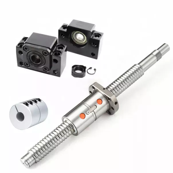
OEM ODM Cardan Shaft for Farm Machine and Agriculture Machine

1. Power or torque related to alternating load you require.  

2. Cross journal(Universal joint) size which decides torque of a PTO Shaft:  

3 Closed overall length (or cross to cross) of a PTO shaft.  

4 Tubes or Pipes  

FAQ

1. Q: Are your products forged or cast?

    A: All of our products are forged.

2. Q: Do you have a CE certificate?
    A: Yes, we are CE qualified.
3. Q: What’s the horse power of the pto shaft are available?
    A: We provide a full range of pto shaft, ranging from 16HP-200HP.
4. Q: How many splined specification do you have ?
    A: We produce 1 1/8″-Z6, 1 3/8″-Z6, 1 3/4″-Z6, 1 3/8″- Z21, 1 3/4″-Z20, 8X42X48X8 and 8X32X38X6 splines.
5. Q: How about the warranty?
    A: We guarantee 1 year warranty. With quality problems, we will send you the new products for free within next shipment.
6. Q: What’s your payment terms?
    A: T/T, L/C, D/A, D/P….
7. Q: What is the delivery time?
    A: 30 days after receiving your advanced deposit.
8. Q: What’s your MOQ?
    A: 50 PCS for each type.

Driveshaft structure and vibrations associated with it

The structure of the drive shaft is critical to its efficiency and reliability. Drive shafts typically contain claw couplings, rag joints and universal joints. Other drive shafts have prismatic or splined joints. Learn about the different types of drive shafts and how they work. If you want to know the vibrations associated with them, read on. But first, let’s define what a driveshaft is.
air-compressor

transmission shaft

As the demand on our vehicles continues to increase, so does the demand on our drive systems. Higher CO2 emission standards and stricter emission standards increase the stress on the drive system while improving comfort and shortening the turning radius. These and other negative effects can place significant stress and wear on components, which can lead to driveshaft failure and increase vehicle safety risks. Therefore, the drive shaft must be inspected and replaced regularly.
Depending on your model, you may only need to replace 1 driveshaft. However, the cost to replace both driveshafts ranges from $650 to $1850. Additionally, you may incur labor costs ranging from $140 to $250. The labor price will depend on your car model and its drivetrain type. In general, however, the cost of replacing a driveshaft ranges from $470 to $1850.
Regionally, the automotive driveshaft market can be divided into 4 major markets: North America, Europe, Asia Pacific, and Rest of the World. North America is expected to dominate the market, while Europe and Asia Pacific are expected to grow the fastest. Furthermore, the market is expected to grow at the highest rate in the future, driven by economic growth in the Asia Pacific region. Furthermore, most of the vehicles sold globally are produced in these regions.
The most important feature of the driveshaft is to transfer the power of the engine to useful work. Drive shafts are also known as propeller shafts and cardan shafts. In a vehicle, a propshaft transfers torque from the engine, transmission, and differential to the front or rear wheels, or both. Due to the complexity of driveshaft assemblies, they are critical to vehicle safety. In addition to transmitting torque from the engine, they must also compensate for deflection, angular changes and length changes.

type

Different types of drive shafts include helical shafts, gear shafts, worm shafts, planetary shafts and synchronous shafts. Radial protruding pins on the head provide a rotationally secure connection. At least 1 bearing has a groove extending along its circumferential length that allows the pin to pass through the bearing. There can also be 2 flanges on each end of the shaft. Depending on the application, the shaft can be installed in the most convenient location to function.
Propeller shafts are usually made of high-quality steel with high specific strength and modulus. However, they can also be made from advanced composite materials such as carbon fiber, Kevlar and fiberglass. Another type of propeller shaft is made of thermoplastic polyamide, which is stiff and has a high strength-to-weight ratio. Both drive shafts and screw shafts are used to drive cars, ships and motorcycles.
Sliding and tubular yokes are common components of drive shafts. By design, their angles must be equal or intersect to provide the correct angle of operation. Unless the working angles are equal, the shaft vibrates twice per revolution, causing torsional vibrations. The best way to avoid this is to make sure the 2 yokes are properly aligned. Crucially, these components have the same working angle to ensure smooth power flow.
The type of drive shaft varies according to the type of motor. Some are geared, while others are non-geared. In some cases, the drive shaft is fixed and the motor can rotate and steer. Alternatively, a flexible shaft can be used to control the speed and direction of the drive. In some applications where linear power transmission is not possible, flexible shafts are a useful option. For example, flexible shafts can be used in portable devices.
air-compressor

put up

The construction of the drive shaft has many advantages over bare metal. A shaft that is flexible in multiple directions is easier to maintain than a shaft that is rigid in other directions. The shaft body and coupling flange can be made of different materials, and the flange can be made of a different material than the main shaft body. For example, the coupling flange can be made of steel. The main shaft body is preferably flared on at least 1 end, and the at least 1 coupling flange includes a first generally frustoconical projection extending into the flared end of the main shaft body.
The normal stiffness of fiber-based shafts is achieved by the orientation of parallel fibers along the length of the shaft. However, the bending stiffness of this shaft is reduced due to the change in fiber orientation. Since the fibers continue to travel in the same direction from the first end to the second end, the reinforcement that increases the torsional stiffness of the shaft is not affected. In contrast, a fiber-based shaft is also flexible because it uses ribs that are approximately 90 degrees from the centerline of the shaft.
In addition to the helical ribs, the drive shaft 100 may also contain reinforcing elements. These reinforcing elements maintain the structural integrity of the shaft. These reinforcing elements are called helical ribs. They have ribs on both the outer and inner surfaces. This is to prevent shaft breakage. These elements can also be shaped to be flexible enough to accommodate some of the forces generated by the drive. Shafts can be designed using these methods and made into worm-like drive shafts.

vibration

The most common cause of drive shaft vibration is improper installation. There are 5 common types of driveshaft vibration, each related to installation parameters. To prevent this from happening, you should understand what causes these vibrations and how to fix them. The most common types of vibration are listed below. This article describes some common drive shaft vibration solutions. It may also be beneficial to consider the advice of a professional vibration technician for drive shaft vibration control.
If you’re not sure if the problem is the driveshaft or the engine, try turning on the stereo. Thicker carpet kits can also mask vibrations. Nonetheless, you should contact an expert as soon as possible. If vibration persists after vibration-related repairs, the driveshaft needs to be replaced. If the driveshaft is still under warranty, you can repair it yourself.
CV joints are the most common cause of third-order driveshaft vibration. If they are binding or fail, they need to be replaced. Alternatively, your CV joints may just be misaligned. If it is loose, you can check the CV connector. Another common cause of drive shaft vibration is improper assembly. Improper alignment of the yokes on both ends of the shaft can cause them to vibrate.
Incorrect trim height can also cause driveshaft vibration. Correct trim height is necessary to prevent drive shaft wobble. Whether your vehicle is new or old, you can perform some basic fixes to minimize problems. One of these solutions involves balancing the drive shaft. First, use the hose clamps to attach the weights to it. Next, attach an ounce of weight to it and spin it. By doing this, you minimize the frequency of vibration.
air-compressor

cost

The global driveshaft market is expected to exceed (xxx) million USD by 2028, growing at a compound annual growth rate (CAGR) of XX%. Its soaring growth can be attributed to several factors, including increasing urbanization and R&D investments by leading market players. The report also includes an in-depth analysis of key market trends and their impact on the industry. Additionally, the report provides a comprehensive regional analysis of the Driveshaft Market.
The cost of replacing the drive shaft depends on the type of repair required and the cause of the failure. Typical repair costs range from $300 to $750. Rear-wheel drive cars usually cost more. But front-wheel drive vehicles cost less than four-wheel drive vehicles. You may also choose to try repairing the driveshaft yourself. However, it is important to do your research and make sure you have the necessary tools and equipment to perform the job properly.
The report also covers the competitive landscape of the Drive Shafts market. It includes graphical representations, detailed statistics, management policies, and governance components. Additionally, it includes a detailed cost analysis. Additionally, the report presents views on the COVID-19 market and future trends. The report also provides valuable information to help you decide how to compete in your industry. When you buy a report like this, you are adding credibility to your work.
A quality driveshaft can improve your game by ensuring distance from the tee and improving responsiveness. The new material in the shaft construction is lighter, stronger and more responsive than ever before, so it is becoming a key part of the driver. And there are a variety of options to suit any budget. The main factor to consider when buying a shaft is its quality. However, it’s important to note that quality doesn’t come cheap and you should always choose an axle based on what your budget can handle.

China factory Tractor Parts Pto Drive Transmission Shaft for Agriculture Machinery     near me supplier China factory Tractor Parts Pto Drive Transmission Shaft for Agriculture Machinery     near me supplier

China factory Tractor Brake Parts Brake Master Cylinder for New Holland/Case 87398198 near me factory

Product Description

Professional Manufacturer of Auto Brake Parts for Trucks & Cars

Full Range, Cover 98% model of Trucks and Cars

Product Description

Brand KOMP / OEM support
Condition Brand New
Minimum Order QTY 50-100 pcs
OEM Order Yes
Stock order Lead-Time 1-15 days
Wholesale order Lead-Time 25-45 days
Warranty 12 month / 30000 km
Packing Plastic bag + Neutral box / Color box + Carton
Shipping DHL, UPS, TNT, FedEx, Aramex, EMS, Air Cargo, Sea Cargo
Payment term Credit Card, Paypal, W/U, T/T, L/C, Money Gram,……


Packaging & Shipping

Plastic bag, Bubble bag, Antirust paper, Color box…anything protective method and customized packing be support

Our Advantages

KOMP has 3 product assembly lines, 20000 pcs products be assembled every day.


KOMP has 1000 m2 warehouse storage of products assembly


KOMP has completed automatic packing workshop


KOMP has a test lab for Endurance verification and High & Low Temperature test


KOMP has self-owned CNC workshop for both rough machinery and fine machinery


KOMP has environment friendly automatic ultrasonic cleaning machine
 

Exhibition & Factory Visit


KOMP travel to attend worldwide exhibitions to establish cooperation with Industry-leading customers in the local markets,
such as Automechanika Frankfurt, 
PAACE Automechanika Mexico, 
APPEX Las Vegas, 
Automechanika South Africa,
……

KOMP warmly welcome to visit our factory, Close face-to-face to the production equipment and processes.


FAQ

1.Are you a trading company or factory?

We are a factory with over 18 years experience, allocate in HangZhou city, ZheJiang Province. CHERY automotive locate here.


2.How to get the catalog of your company

You can leave your message on the right-hand with the OE number, basic description and contact info, we’ll feedback you in 7D/24H.


3.What kind of certificate of your factory?

We are qualified with IATF-16949.


4.Can you use my package design?

No problem, customized package is support based on your certificate of trademark registration and authorization.


5.What’s your brake cylinder quality guarantee?

Normally the guarantee is 12 months or 30,000 km.


6.What’s your minimum order quantity?

Our MOQ is 200 to 300PCS, and even 1pcs could be sale for trail if has stock.


7.How long it takes to deliver goods after place an order?

In stock goods take about 1-5 days for shipping.No stock goods take about 30-60 days for shipping.

Ball Screws – Dimensions, Applications, and Benefits

Ball screws are popular, lightweight, precision mechanical components. They are commonly used in machinery, gears, and knurled objects. These screw-like parts can be easily maintained and lubricated using oil. This article discusses their dimensions, applications, and benefits. The following sections provide additional information to help you select the right ball screw for your needs. We’ll discuss some of the important characteristics of ball screws and what makes them so useful.
air-compressor

Preloading

A key problem with nut-to-ball screw backlash is the ability of the nut to move freely on the threads of the ball screw. To solve this problem, a patented solution was developed. The patent, 4,557,156, describes an innovative method for preloading ball screws and nuts. By applying a preloading nut, the threads of the ball screw are prevented from moving back and forth with the nut.
A mechanical design that involves axial play involves a lot of mass, inertia, and complexity. These characteristics lead to wear and rust problems. Preloading ball screws using a dynamic system reduces mechanical complexity by allowing preload to be adjusted while the mechanism is running. This also reduces the number of mechanical parts and simplifies manufacturing. Thus, the preloading method of the present invention is advantageous.
The servo motors used in the system monitor the output torque and adjust the power to 1 motor in a dynamic way, thus creating a torque differential between the balls. This torque differential in turn creates a preload force between the ball nuts. The servo motors’ output torque is controlled in this manner, and the machine’s backlash clearance can be precisely controlled. Hence, the machine can perform multiple tasks with increased precision.
Several prior art methods for preloading ball screws are described in detail in FIG. 3. The helical thread grooves of the ball screw 26 and the nut 24 define a pathway for roller balls to travel along. The stylized broken line indicates the general position of the axis of the ball roller screw 26. The corresponding ball screws are used in a number of applications. This technique may be used to manufacture custom-sized screws.

Lubrication

Ball screws are mechanical elements that roll balls through a groove. Improper lubrication can reduce the life of these screw elements. Improper lubrication can lead to shaft damage, malfunction, and decreased performance. This article discusses the importance of proper lubrication and how to do it. You can learn how to properly lubricate ball screws in the following paragraphs. Here are some tips to ensure long-term performance and safety of ball screws.
The first thing you should do is determine the type of lubricant you’ll be using. Oils are preferred because they tend to remain inside the ball nut, and grease can build up in it. Oils also tend to have better anti-corrosion properties than grease. However, grease is more likely to be clogged with debris than oils. So, before you choose the lubricant that’s right for your screw, make sure you wash it off.
The oil used in ball screw lubrication must be applied at a controlled rate. It can prevent metal-on-metal contact and clean out contaminants as it passes through the ball nut. However, oil as a lubricant is expensive and can contaminate the process if it mixes with the cutting fluid. Grease, on the other hand, is inexpensive, requires fewer applications, and does not contaminate process fluids.
If you use a synthetic oil for lubrication, make sure to choose a viscosity that is appropriate for the operating temperature. Oil viscosity can increase the temperature of the ball screw assembly, and excessive oil can reduce its life. A correct amount of oil will reduce the temperature of the ball screw assembly, while too little will increase friction and wear. Use the following guidelines to determine the right amount of oil for your screw.
air-compressor

Dimensions

Dimensions of ball screws are a very important aspect to consider when determining the best type for your application. Technical acceptance conditions for ball screws specify the allowed deviations during acceptance tests. The tolerance class can also change, depending on the needs of a specific application. The following table lists the most important tolerance values for the full range of screw lengths. This table is a helpful guide when looking for a specific screw. The table below lists the dimensions of common ball screws.
The axial load applied to a ball screw is 0.5 x Fpr / 2Fpr. The minimum screw diameter is known as the root diameter. The axial load causes the screw shaft to deform in a certain way (DL1 and DL2). The elastic deflection induced by the load on a ball screw is called its rigidity. This rigidity is important for calculating sizing parameters for a ball screw.
The preload value of the ball screw affects the dynamic load capacity. A preload of 10 percent is considered adequate, while a value greater than this may compromise the screw’s durability. In general, a high preload value will result in a lower dynamic load capacity and greater wear. However, the preload value must be calculated with the relevant screw parameters. This is because a high preload value reduces the screw’s durability.
To ensure that your screw meets the specified parameters, the dynamic load capacity must be calculated. This is the amount of force a ball screw will withstand under a specified load. This calculation also includes strength checks. If you are using a ball screw for applications that need extra strength, it may require a safety factor. For example, if the screw is used for double-axial mounting, then the outer ball nut must be inserted into the nut, causing a secondary load.

Applications

The present invention provides a simple, yet highly effective way to mount a ball screw. Its absence of insert slots or through holes makes it simpler to assemble and provides a more uniform nut. The lack of mechanical features also reduces heat treatment issues, and the nut’s hardness can be uniformly hardened. As a result, the screw’s overall performance is improved. Here are some examples of applications for ball screws.
Preloading is the process of applying force to a ball screw. This increases the rigidity of the screw assembly and eliminates backlash, which is lost motion caused by clearance between the nut and ball. Backlash disrupts repeatability and accuracy. Spacer preloading involves inserting force between 2 ball nuts and transmitting it through the grooves. This method is ideal when preloading is needed in large quantities. In addition to increasing rigidity, preloading can improve accuracy.
Ball screws require careful care in their working surfaces to prevent contamination. Rubber or leather bellows can be used to protect their surfaces, while positive air pressure can be applied to the screw. Preloading eliminates backlash, a common problem among screw assemblies. In addition to the numerous applications for ball screws, they are also critical to computer-controlled motion-control systems and wire bonding. And there are many more examples. So what are the benefits of using these devices?
The spring preloading system uses a spring in between 2 ball nuts, applying tensional forces to the ball nuts. This spring creates grooves in the nut’s middle, which facilitates recirculation of the balls. The spring preloading mechanism is more compact than the double nut mechanism, but the lengthening of the lead reduces the ball screw’s load capacity. Its compact design makes it ideal for small clearance assemblies.
air-compressor

Maintenance

In addition to performing maintenance tasks yourself, the manufacturer of ball screws should offer reverse engineering services that will enable them to identify specific problems. The process of reverse engineering allows ball screw manufacturers to develop new ball screws and parts. In the event that a ball screw is beyond repair, a manufacturer can often save a significant amount of money by repairing it instead of replacing it. In addition to repairing a ball screw, the manufacturer should also offer free evaluation services for the component. Reconditioning and replacement involve the use of new parts, while reloading and replacement replace the screw.
Performing routine maintenance checks on ball screw assemblies is essential for maintaining optimal performance and extending their service life. Overtime, excessive wear can lead to a variety of problems, including backlash, vibration, and ball bearing noise. In addition, the increased friction increases the required torque for turning a screw, causing system failure and significant downtime. To ensure that a ball screw is fully functional, it must be checked for wear and maintain the proper lubrication system.
Discoloration or pitting on a ball screw indicates that it is in need of repair. The same is true if there are chatter marks in the ball groove. Oftentimes, a ball screw needs a new lubrication seal or wipers. Additionally, it may be missing or over-wearing, which could result in permanent failure. Finally, excessive power draw could be a sign of improper lubrication or improper installation.
Proper maintenance is essential for any machine tool. When performed properly, machine tools can last decades with continuous use. Proper care and maintenance is essential to ensure long life and optimal performance. In addition to improving machine tool uptime, proper maintenance affects the accuracy and repeatability of the end product. Therefore, premium machine tool manufacturers focus on the performance and durability of ball screws. They develop innovative designs and lubricants to optimize the lifespan of their products.

China factory Tractor Brake Parts Brake Master Cylinder for New Holland/Case 87398198     near me factory China factory Tractor Brake Parts Brake Master Cylinder for New Holland/Case 87398198     near me factory

China manufacturer Agricultural Tractor Spare Parts Manufactor Professional Notched Harrow Disc near me shop

Product Description

Types of disc: Notched/Plain/Smooth/Flat
Material: 65 Manganese Steel
Diameter: 12″-32″
Thickness: 3-12 mm
Hardness: 38 to 45 HRC

Our company is a professional manufacturer of plough and harrow disc blades. We have a production line for farming discs producing, cleaning and painting.

We can produce discs made of 65 Manganese Steel from in 12″-32″
Diameter and from 3 to 12mm in thickness. Annually output is 300, 000 PCS. The products exported to UK, USA, France, Australia and South Africa, etc. More than 60 countries and districts.

We can supply all various of discs according to customers drawings and samples.

Diameter Overall dimension Thickness
mm inch mm mm
305 12 19 3
330 13 25 3
355 14 38 3
410 15 38~50 3
430 17 57 3; 4
460 18 38~60 3; 4
480 19 57 3; 4
510 20 44~63 3; 4; 5
535 21 63 3; 4; 5
560 22 60~85 4; 5; 6
585 23 75~90 4; 5; 6
610 24 75~95 4; 5; 6
660 26 86~115 5; 6; 7; 8
710 28 100~130 5; 6; 7; 8
760 30 120~135 6; 7; 8; 10; 12
810 32 120~140 8; 10; 12


How to Contact Us?


Send your Inquiry Details in the Below for sample, Click “Send” Now!

How to Replace the Drive Shaft

Several different functions in a vehicle are critical to its functioning, but the driveshaft is probably the part that needs to be understood the most. A damaged or damaged driveshaft can damage many other auto parts. This article will explain how this component works and some of the signs that it may need repair. This article is for the average person who wants to fix their car on their own but may not be familiar with mechanical repairs or even driveshaft mechanics. You can click the link below for more information.
air-compressor

Repair damaged driveshafts

If you own a car, you should know that the driveshaft is an integral part of the vehicle’s driveline. They ensure efficient transmission of power from the engine to the wheels and drive. However, if your driveshaft is damaged or cracked, your vehicle will not function properly. To keep your car safe and running at peak efficiency, you should have it repaired as soon as possible. Here are some simple steps to replace the drive shaft.
First, diagnose the cause of the drive shaft damage. If your car is making unusual noises, the driveshaft may be damaged. This is because worn bushings and bearings support the drive shaft. Therefore, the rotation of the drive shaft is affected. The noise will be squeaks, dings or rattles. Once the problem has been diagnosed, it is time to repair the damaged drive shaft.
Professionals can repair your driveshaft at relatively low cost. Costs vary depending on the type of drive shaft and its condition. Axle repairs can range from $300 to $1,000. Labor is usually only around $200. A simple repair can cost between $150 and $1700. You’ll save hundreds of dollars if you’re able to fix the problem yourself. You may need to spend a few more hours educating yourself about the problem before handing it over to a professional for proper diagnosis and repair.
The cost of repairing a damaged driveshaft varies by model and manufacturer. It can cost as much as $2,000 depending on parts and labor. While labor costs can vary, parts and labor are typically around $70. On average, a damaged driveshaft repair costs between $400 and $600. However, these parts can be more expensive than that. If you don’t want to spend money on unnecessarily expensive repairs, you may need to pay a little more.
air-compressor

Learn how drive shafts work

While a car engine may be 1 of the most complex components in your vehicle, the driveshaft has an equally important job. The driveshaft transmits the power of the engine to the wheels, turning the wheels and making the vehicle move. Driveshaft torque refers to the force associated with rotational motion. Drive shafts must be able to withstand extreme conditions or they may break. Driveshafts are not designed to bend, so understanding how they work is critical to the proper functioning of the vehicle.
The drive shaft includes many components. The CV connector is 1 of them. This is the last stop before the wheels spin. CV joints are also known as “doughnut” joints. The CV joint helps balance the load on the driveshaft, the final stop between the engine and the final drive assembly. Finally, the axle is a single rotating shaft that transmits power from the final drive assembly to the wheels.
Different types of drive shafts have different numbers of joints. They transmit torque from the engine to the wheels and must accommodate differences in length and angle. The drive shaft of a front-wheel drive vehicle usually includes a connecting shaft, an inner constant velocity joint and an outer fixed joint. They also have anti-lock system rings and torsional dampers to help them run smoothly. This guide will help you understand the basics of driveshafts and keep your car in good shape.
The CV joint is the heart of the driveshaft, it enables the wheels of the car to move at a constant speed. The connector also helps transmit power efficiently. You can learn more about CV joint driveshafts by looking at the top 3 driveshaft questions
The U-joint on the intermediate shaft may be worn or damaged. Small deviations in these joints can cause slight vibrations and wobble. Over time, these vibrations can wear out drivetrain components, including U-joints and differential seals. Additional wear on the center support bearing is also expected. If your driveshaft is leaking oil, the next step is to check your transmission.
The drive shaft is an important part of the car. They transmit power from the engine to the transmission. They also connect the axles and CV joints. When these components are in good condition, they transmit power to the wheels. If you find them loose or stuck, it can cause the vehicle to bounce. To ensure proper torque transfer, your car needs to stay on the road. While rough roads are normal, bumps and bumps are common.
air-compressor

Common signs of damaged driveshafts

If your vehicle vibrates heavily underneath, you may be dealing with a faulty propshaft. This issue limits your overall control of the vehicle and cannot be ignored. If you hear this noise frequently, the problem may be the cause and should be diagnosed as soon as possible. Here are some common symptoms of a damaged driveshaft. If you experience this noise while driving, you should have your vehicle inspected by a mechanic.
A clanging sound can also be 1 of the signs of a damaged driveshaft. A ding may be a sign of a faulty U-joint or center bearing. This can also be a symptom of worn center bearings. To keep your vehicle safe and functioning properly, it is best to have your driveshaft inspected by a certified mechanic. This can prevent serious damage to your car.
A worn drive shaft can cause difficulty turning, which can be a major safety issue. Fortunately, there are many ways to tell if your driveshaft needs service. The first thing you can do is check the u-joint itself. If it moves too much or too little in any direction, it probably means your driveshaft is faulty. Also, rust on the bearing cap seals may indicate a faulty drive shaft.
The next time your car rattles, it might be time for a mechanic to check it out. Whether your vehicle has a manual or automatic transmission, the driveshaft plays an important role in your vehicle’s performance. When 1 or both driveshafts fail, it can make the vehicle unsafe or impossible to drive. Therefore, you should have your car inspected by a mechanic as soon as possible to prevent further problems.
Your vehicle should also be regularly lubricated with grease and chain to prevent corrosion. This will prevent grease from escaping and causing dirt and grease to build up. Another common sign is a dirty driveshaft. Make sure your phone is free of debris and in good condition. Finally, make sure the driveshaft chain and cover are in place. In most cases, if you notice any of these common symptoms, your vehicle’s driveshaft should be replaced.
Other signs of a damaged driveshaft include uneven wheel rotation, difficulty turning the car, and increased drag when trying to turn. A worn U-joint also inhibits the ability of the steering wheel to turn, making it more difficult to turn. Another sign of a faulty driveshaft is the shuddering noise the car makes when accelerating. Vehicles with damaged driveshafts should be inspected as soon as possible to avoid costly repairs.

China manufacturer Agricultural Tractor Spare Parts Manufactor Professional Notched Harrow Disc     near me shop China manufacturer Agricultural Tractor Spare Parts Manufactor Professional Notched Harrow Disc     near me shop

China Best Sales Heavy Truck Trailer Parts Widely Application Square Axle 13ton 16ton Trailer Axle for Semi Trailer Parts Semi Trailer Tractor Truck German Axle near me shop

Product Description

Recommended Spring Seat
FB(mm) C/D/∅(mm)
75 100/180/24
90 115/180/27
100 125/180/27

Axle Type Max Capacity
(kg)
Brake Size
(mm)
Track
TR(mm)
Spring Seat
LM(mm)
Axle Beam
(mm)
GM
(mm)
Wheel Fixing Total Length
LP(mm)
Weight
(kg)
Bearing
Studs P.C.D. ∅H(mm)
ZI12GA-1 12,000 420×180 1820 ≤435 127 402 10-M22x1.5 ISO 335 281 2135 335 33213  33118
ZI12GA-2 12,000 420×180 1840 ≤455 150 422 10-M22x1.5 ISO 335 281 2155 360 33213  33118
ZI12GA-3 12,000 420×200 1840 ≤455 150 354 10-M22x1.5 ISO 335 281 2155 373 33213  33118
ZI12GA-4 12,000 420×180 2040 ≤455 150 622 8xM20X1.5 JIS 285.75 281 2355 375 33213  33118
ZI12GA-5 14,000 420×200 1840 ≤455 150 354 10-M22x1.5 ISO 335 281 2185 410 33215  32219
ZI12GA-6 14,000 420×220 1840 ≤455 150 354 10-M22x1.5 ISO 335 281 2185 415 33215  32219
ZI12GA-7 16,000 420×200 1850 ≤455 150 356 10-M22x1.5 ISO 335 281 2240 442 32314  32222
ZI12GA-8 16,000 420×220 1850 ≤455 150 376 10-M22x1.5 ISO 335 281 2240 455 32314  32222
ZI12GA-9 18,000 420×220 1850 ≤455 150 376 10-M22x1.5 ISO 335 281 2240 475 32314  32222


The Benefits of Spline Couplings for Disc Brake Mounting Interfaces

Spline couplings are commonly used for securing disc brake mounting interfaces. Spline couplings are often used in high-performance vehicles, aeronautics, and many other applications. However, the mechanical benefits of splines are not immediately obvious. Listed below are the benefits of spline couplings. We’ll discuss what these advantages mean for you. Read on to discover how these couplings work.

Disc brake mounting interfaces are splined

There are 2 common disc brake mounting interfaces – splined and six-bolt. Splined rotors fit on splined hubs; six-bolt rotors will need an adapter to fit on six-bolt hubs. The six-bolt method is easier to maintain and may be preferred by many cyclists. If you’re thinking of installing a disc brake system, it is important to know how to choose the right splined and center lock interfaces.
splineshaft

Aerospace applications

The splines used for spline coupling in aircraft are highly complex. While some previous researches have addressed the design of splines, few publications have tackled the problem of misaligned spline coupling. Nevertheless, the accurate results we obtained were obtained using dedicated simulation tools, which are not commercially available. Nevertheless, such tools can provide a useful reference for our approach. It would be beneficial if designers could use simple tools for evaluating contact pressure peaks. Our analytical approach makes it possible to find answers to such questions.
The design of a spline coupling for aerospace applications must be accurate to minimize weight and prevent failure mechanisms. In addition to weight reduction, it is necessary to minimize fretting fatigue. The pressure distribution on the spline coupling teeth is a significant factor in determining its fretting fatigue. Therefore, we use analytical and experimental methods to examine the contact pressure distribution in the axial direction of spline couplings.
The teeth of a spline coupling can be categorized by the type of engagement they provide. This study investigates the position of resultant contact forces in the teeth of a spline coupling when applied to pitch diameter. Using FEM models, numerical results are generated for nominal and parallel offset misalignments. The axial tooth profile determines the behavior of the coupling component and its ability to resist wear. Angular misalignment is also a concern, causing misalignment.
In order to assess wear damage of a spline coupling, we must take into consideration the impact of fretting on the components. This wear is caused by relative motion between the teeth that engage them. The misalignment may be caused by vibrations, cyclical tooth deflection, or angular misalignment. The result of this analysis may help designers improve their spline coupling designs and develop improved performance.
CZPT polyimide, an abrasion-resistant polymer, is a popular choice for high-temperature spline couplings. This material reduces friction and wear, provides a low friction surface, and has a low wear rate. Furthermore, it offers up to 50 times the life of metal on metal spline connections. For these reasons, it is important to choose the right material for your spline coupling.
splineshaft

High-performance vehicles

A spline coupler is a device used to connect splined shafts. A typical spline coupler resembles a short pipe with splines on either end. There are 2 basic types of spline coupling: single and dual spline. One type attaches to a drive shaft, while the other attaches to the gearbox. While spline couplings are typically used in racing, they’re also used for performance problems.
The key challenge in spline couplings is to determine the optimal dimension of spline joints. This is difficult because no commercial codes allow the simulation of misaligned joints, which can destroy components. This article presents analytical approaches to estimating contact pressures in spline connections. The results are comparable with numerical approaches but require special codes to accurately model the coupling operation. This research highlights several important issues and aims to make the application of spline couplings in high-performance vehicles easier.
The stiffness of spline assemblies can be calculated using tooth-like structures. Such splines can be incorporated into the spline joint to produce global stiffness for torsional vibration analysis. Bearing reactions are calculated for a certain level of misalignment. This information can be used to design bearing dimensions and correct misalignment. There are 3 types of spline couplings.
Major diameter fit splines are made with tightly controlled outside diameters. This close fit provides concentricity transfer from the male to the female spline. The teeth of the male spline usually have chamfered tips and clearance with fillet radii. These splines are often manufactured from billet steel or aluminum. These materials are renowned for their strength and uniform grain created by the forging process. ANSI and DIN design manuals define classes of fit.
splineshaft

Disc brake mounting interfaces

A spline coupling for disc brake mounting interfaces is a type of hub-to-brake-disc mount. It is a highly durable coupling mechanism that reduces heat transfer from the disc to the axle hub. The mounting arrangement also isolates the axle hub from direct contact with the disc. It is also designed to minimize the amount of vehicle downtime and maintenance required to maintain proper alignment.
Disc brakes typically have substantial metal-to-metal contact with axle hub splines. The discs are held in place on the hub by intermediate inserts. This metal-to-metal contact also aids in the transfer of brake heat from the brake disc to the axle hub. Spline coupling for disc brake mounting interfaces comprises a mounting ring that is either a threaded or non-threaded spline.
During drag brake experiments, perforated friction blocks filled with various additive materials are introduced. The materials included include Cu-based powder metallurgy material, a composite material, and a Mn-Cu damping alloy. The filling material affects the braking interface’s wear behavior and friction-induced vibration characteristics. Different filling materials produce different types of wear debris and have different wear evolutions. They also differ in their surface morphology.
Disc brake couplings are usually made of 2 different types. The plain and HD versions are interchangeable. The plain version is the simplest to install, while the HD version has multiple components. The two-piece couplings are often installed at the same time, but with different mounting interfaces. You should make sure to purchase the appropriate coupling for your vehicle. These interfaces are a vital component of your vehicle and must be installed correctly for proper operation.
Disc brakes use disc-to-hub elements that help locate the forces and displace them to the rim. These elements are typically made of stainless steel, which increases the cost of manufacturing the disc brake mounting interface. Despite their benefits, however, the high braking force loads they endure are hard on the materials. Moreover, excessive heat transferred to the intermediate elements can adversely affect the fatigue life and long-term strength of the brake system.

China Best Sales Heavy Truck Trailer Parts Widely Application Square Axle 13ton 16ton Trailer Axle for Semi Trailer Parts Semi Trailer Tractor Truck German Axle     near me shop China Best Sales Heavy Truck Trailer Parts Widely Application Square Axle 13ton 16ton Trailer Axle for Semi Trailer Parts Semi Trailer Tractor Truck German Axle     near me shop

China Custom Wholesale Price 44310-2200 H07D Auto Parts Hydraulic Power Steering Pump for Hino Bus Tractor Truck Parts near me manufacturer

Product Description


GREEN Hydraulic
 is 1 strength Professional enterprise which integrates in Hydraulic Component with more than 15 years experience focusing on the abroad and Domestic Market. Our products including Piston Pump, Vane Pump, Gear Pump, Hydraulic Valve, Hydraulic Motor, Electric Motor, Oil Cooler, Accumulator and other hydraulic accessories etc. GREEN Hydraulic Piston Pump Series including CY, A2F, A2FO, A7V, A4V, A10V Series, which is the same as Orignal Rexroth, the same appreance, mounting size and working perofrmance. The products are widely used in machine tool, forging machinery, metallurgy machinery, engineering machinery, mine machinery and other hydraulic systems. They also can be used as hydraulic motors if the valve plate is changed into motor type. GREEN also supply replacement parts for Komatsu, Rexroth, Sauer, Hitachi, Catpillar, KYB, Kawasaki, Toshiba, Linde, Vickers, Yuekn, Nachi…Please consult online customer service for more models

The Benefits of Using Self-Lubricating Bushings for Your Next Pivot

Like any other auto part, control arm bushings wear out over time. This results in an increase in irritating vibrations that can be dangerous in severe cases. The bushings in the control arms also wear out due to the stress that extreme driving conditions put on the control arms. Additionally, environmental factors and oversized tires tend to transmit more vibration through the bushing than conventionally sized tires. Whatever the cause, bushings can be the source of many problems.
bushing

wear and cracking

The main cause of dry valve side bushing cracking is a mismatch in thermal expansion of the core and flange. This situation can seriously compromise the safety of the power system. To improve the safety of dry valve side bushings, the crack development of epoxy impregnated paper under various conditions was investigated. A coupled thermomechanical simulation model was also used to study the cracking process.
The first step in diagnosing the cause of bushing wear and cracking is a visual inspection. The bushing of the lower control arm is fixed to the frame by a bracket. If there are any visible cracks, it’s time to replace the bushing. However, there is no need to replace the entire suspension. In some cases, worn bushings can cause a variety of problems, including body lean, excessive tire wear and cornering noise.

Maintenance free

If you’re considering maintenance-free bushings for your next pivot, you’ll be wondering what to look for in these components. The bushing protects the housing from corrosion and keeps the bushing under pressure. However, many users are not familiar with what these components can do for their applications. In this article, we’ll look at several examples of truly maintenance-free pivots and discuss their requirements.
One of the most popular types of maintenance-free bushings are flanged and parallel. Unlike worm gear bushings, these self-lubricating metal bearings are ideal for a variety of applications and conditions. They reduce failure and downtime costs while providing the long-term lubrication required by other types of bushings. Since these sleeves are made of lead-free material, they are RoHS compliant, which means they are environmentally friendly.Another common maintenance-free bushing is plastic. This material is easier to find off-the-shelf and relatively inexpensive to produce. However, it is not suitable for high load applications as it will crack under heavy loads and damage mating parts. Plastics can also deviate if the manufacturing process is imprecise. Plastic bushings can also crack when subjected to high loads.
bushing

self-lubricating

When using a self-lubricating bushing, there is no need to apply grease to the bushing. Oily liquids tend to attract dirt and grit, which can wear away the graphite prematurely. By eliminating the need for regular lubrication, you will reduce equipment maintenance costs. This article will explore the benefits of self-lubricating bushings. You will love your kindness.
Self-lubricating bushings have a strong base material to withstand radial bearing pressure while providing shaft support at the contact surfaces. The material also has good fatigue properties and low friction motion. Self-lubricating bushings can be used in environments with high temperatures and aggressive media. These products can also withstand enormous pressure. When using self-lubricating bushings, it is important to select the correct material.
The main advantage of using self-lubricating bushings is ease of maintenance. They don’t require oil to run and are cheaper to buy. Their main benefit is that they can significantly reduce your machine running costs. These bearings do not require oiling operations, reducing maintenance costs. These bearings also offer a simplified mechanical design due to their thin walls and high load capacity. In addition, they reduce noise levels while maintaining excellent wear resistance. Plus, their materials are ROHS compliant, which means they don’t require oil.
Hydropower installations are another area where self-lubricating bushings have proven their advantages. They reduce maintenance costs, extend equipment life, and improve environmental benefits. For example, the Newfoundland Power Company uses self-lubricating bushings in the gates of its hydroelectric power plants. These self-lubricating bushings eliminate grease from entering waterways and tailraces. As a result, power companies are able to reduce maintenance and costs.

compared to cartilage in the human body

What is the difference between tendon, bone and cartilage? Human cartilage is composed of collagen and elastic fibers. In contrast, fibrocartilage contains more collagen than hyaline cartilage. Both cartilage types are composed of proteoglycans, which have a protein backbone and glycosaminoglycan side chains. These components work together to provide structure and flexibility to the cartilage.
Bone is a combination of living and dead cells embedded in a matrix. The outer hard layer of bone is dense bone, and the inner layer is spongy, containing bone marrow, blood vessels, nerves, etc. Bone contains both organic and inorganic substances, and this process of hardening of the matrix produces bone. On the other hand, cartilage consists of chondrocytes and a matrix composed of collagen and elastin fibers. Compared to bone, cartilage is yellow and contains elastic fibers.
Although bone and cartilage are structurally identical, cartilage is more flexible. It is mainly found in the joints and respiratory system and requires flexibility. Its ingredients include collagen and proteoglycans, which provide compression and abrasion resistance. Furthermore, connective tissue is composed of cells, fibers and matrix.
The basic substance of cartilage is chondroitin sulfate, which is derived from animals. Although cartilage grows more slowly than bone, its microstructure is less organized. There is a fibrous sheath covering the cartilage, called the perichondrium. The molecular composition of the ECM plays an important role in the function of cartilage. The collagen matrix is ​​important for cartilage remodeling and consists of changes in the collagen matrix.
bushing

Compared to metal-on-bone contact

Both metal-on-bone contact are known to cause a significant increase in the pressures in a joint. To compare the two, we first calculated the joint contact pressures in each model and compared them. The results of this study support previous research on this subject. The following sections discuss the benefits of both types of contact. They also outline some key differences between the two.

China Custom Wholesale Price 44310-2200 H07D Auto Parts Hydraulic Power Steering Pump for Hino Bus Tractor Truck Parts     near me manufacturer China Custom Wholesale Price 44310-2200 H07D Auto Parts Hydraulic Power Steering Pump for Hino Bus Tractor Truck Parts     near me manufacturer

China Professional Good Price 7673 955 804 303 Eicher 34071539001 Auto Parts Hydraulic Power Steering Pump Tata for Tractor Truck Parts near me manufacturer

Product Description


GREEN Hydraulic
 is 1 strength Professional enterprise which integrates in Hydraulic Component with more than 15 years experience focusing on the abroad and Domestic Market. Our products including Piston Pump, Vane Pump, Gear Pump, Hydraulic Valve, Hydraulic Motor, Electric Motor, Oil Cooler, Accumulator and other hydraulic accessories etc. GREEN Hydraulic Piston Pump Series including CY, A2F, A2FO, A7V, A4V, A10V Series, which is the same as Orignal Rexroth, the same appreance, mounting size and working perofrmance. The products are widely used in machine tool, forging machinery, metallurgy machinery, engineering machinery, mine machinery and other hydraulic systems. They also can be used as hydraulic motors if the valve plate is changed into motor type. GREEN also supply replacement parts for Komatsu, Rexroth, Sauer, Hitachi, Catpillar, KYB, Kawasaki, Toshiba, Linde, Vickers, Yuekn, Nachi…Please consult online customer service for more models

Types of Screw Shafts

Screw shafts come in various types and sizes. These types include fully threaded, Lead, and Acme screws. Let’s explore these types in more detail. What type of screw shaft do you need? Which 1 is the best choice for your project? Here are some tips to choose the right screw:

Machined screw shaft

The screw shaft is a basic piece of machinery, but it can be further customized depending on the needs of the customer. Its features include high-precision threads and ridges. Machined screw shafts are generally manufactured using high-precision CNC machines or lathes. The types of screw shafts available vary in shape, size, and material. Different materials are suitable for different applications. This article will provide you with some examples of different types of screw shafts.
Ball screws are used for a variety of applications, including mounting machines, liquid crystal devices, measuring devices, and food and medical equipment. Various shapes are available, including miniature ball screws and nut brackets. They are also available without keyway. These components form a high-accuracy feed mechanism. Machined screw shafts are also available with various types of threaded ends for ease of assembly. The screw shaft is an integral part of linear motion systems.
When you need a machined screw shaft, you need to know the size of the threads. For smaller machine screws, you will need a mating part. For smaller screw sizes, the numbers will be denominated as industry Numeric Sizes. These denominations are not metric, but rather in mm, and they may not have a threads-per-inch designation. Similarly, larger machine screws will usually have threads that have a higher pitch than those with a lower pitch.
Another important feature of machine screws is that they have a thread on the entire shaft, unlike their normal counterparts. These machine screws have finer threads and are intended to be screwed into existing tapped holes using a nut. This means that these screws are generally stronger than other fasteners. They are usually used to hold together electronic components, industrial equipment, and engines. In addition to this, machine screws are usually made of a variety of materials.
screwshaft

Acme screw

An Acme screw is the most common type of threaded shaft available. It is available in a variety of materials including stainless steel and carbon steel. In many applications, it is used for large plates in crushing processes. ACME screws are self-locking and are ideal for applications requiring high clamping force and low friction. They also feature a variety of standard thread forms, including knurling and rolled worms.
Acme screws are available in a wide range of sizes, from 1/8″ to 6″. The diameter is measured from the outside of the screw to the bottom of the thread. The pitch is equal to the lead in a single start screw. The lead is equal to the pitch plus the number of starts. A screw of either type has a standard pitch and a lead. Acme screws are manufactured to be accurate and durable. They are also widely available in a wide range of materials and can be customized to fit your needs.
Another type of Acme screw is the ball screw. These have no back drive and are widely used in many applications. Aside from being lightweight, they are also able to move at faster speeds. A ball screw is similar to an Acme screw, but has a different shape. A ball screw is usually longer than an Acme screw. The ball screw is used for applications that require high linear speeds. An Acme screw is a common choice for many industries.
There are many factors that affect the speed and resolution of linear motion systems. For example, the nut position and the distance the screw travels can all affect the resolution. The total length of travel, the speed, and the duty cycle are all important. The lead size will affect the maximum linear speed and force output. If the screw is long, the greater the lead size, the higher the resolution. If the lead length is short, this may not be the most efficient option.
screwshaft

Lead screw

A lead screw is a threaded mechanical device. A lead screw consists of a cylindrical shaft, which includes a shallow thread portion and a tightly wound spring wire. This spring wire forms smooth, hard-spaced thread convolutions and provides wear-resistant engagement with the nut member. The wire’s leading and trailing ends are anchored to the shaft by means appropriate to the shaft’s composition. The screw is preferably made of stainless steel.
When selecting a lead screw, 1 should first determine its critical speed. The critical speed is the maximum rotations per minute based on the natural frequency of the screw. Excessive backlash will damage the lead screw. The maximum number of revolutions per minute depends on the screw’s minor diameter, length, assembly alignment, and end fixity. Ideally, the critical speed is 80% of its evaluated critical speed. A critical speed is not exceeded because excessive backlash would damage the lead screw and may be detrimental to the screw’s performance.
The PV curve defines the safe operating limits of a lead screw. This relationship describes the inverse relationship between contact surface pressure and sliding velocity. As the PV value increases, a lower rotation speed is required for heavier axial loads. Moreover, PV is affected by material and lubrication conditions. Besides, end fixity, which refers to the way the lead screw is supported, also affects its critical speed. Fixed-fixed and free end fixity are both possible.
Lead screws are widely used in industries and everyday appliances. In fact, they are used in robotics, lifting equipment, and industrial machinery. High-precision lead screws are widely used in the fields of engraving, fluid handling, data storage, and rapid prototyping. Moreover, they are also used in 3D printing and rapid prototyping. Lastly, lead screws are used in a wide range of applications, from measuring to assembly.

Fully threaded screw

A fully threaded screw shaft can be found in many applications. Threading is an important feature of screw systems and components. Screws with threaded shafts are often used to fix pieces of machinery together. Having fully threaded screw shafts ensures that screws can be installed without removing the nut or shaft. There are 2 major types of screw threads: coarse and fine. When it comes to coarse threads, UTS is the most common type, followed by BSP.
In the 1840s, a British engineer named Joseph Whitworth created a design that was widely used for screw threads. This design later became the British Standard Whitworth. This standard was used for screw threads in the United States during the 1840s and 1860s. But as screw threads evolved and international standards were established, this system remained largely unaltered. A new design proposed in 1864 by William Sellers improved upon Whitworth’s screw threads and simplified the pitch and surface finish.
Another reason for using fully threaded screws is their ability to reduce heat. When screw shafts are partially threaded, the bone grows up to the screw shaft and causes the cavity to be too narrow to remove it. Consequently, the screw is not capable of backing out. Therefore, fully threaded screws are the preferred choice for inter-fragmentary compression in children’s fractures. However, surgeons should know the potential complication when removing metalwork.
The full thread depth of a fully threaded screw is the distance at which a male thread can freely thread into the shaft. This dimension is typically 1 millimeter shy of the total depth of the drilled hole. This provides space for tap lead and chips. The full-thread depth also makes fully threaded screws ideal for axially-loaded connections. It is also suitable for retrofitting applications. For example, fully threaded screws are commonly used to connect 2 elements.
screwshaft

Ball screw

The basic static load rating of a ball screw is determined by the product of the maximum axial static load and the safety factor “s0”. This factor is determined by past experience in similar applications and should be selected according to the design requirements of the application. The basic static load rating is a good guideline for selecting a ball screw. There are several advantages to using a ball screw for a particular application. The following are some of the most common factors to consider when selecting a ball screw.
The critical speed limit of a ball screw is dependent on several factors. First of all, the critical speed depends on the mass, length and diameter of the shaft. Second, the deflection of the shaft and the type of end bearings determine the critical speed. Finally, the unsupported length is determined by the distance between the ball nut and end screw, which is also the distance between bearings. Generally, a ball screw with a diameter greater than 1.2 mm has a critical speed limit of 200 rpm.
The first step in manufacturing a high-quality ball screw is the choice of the right steel. While the steel used for manufacturing a ball screw has many advantages, its inherent quality is often compromised by microscopic inclusions. These microscopic inclusions may eventually lead to crack propagation, surface fatigue, and other problems. Fortunately, the technology used in steel production has advanced, making it possible to reduce the inclusion size to a minimum. However, higher-quality steels can be expensive. The best material for a ball screw is vacuum-degassed pure alloy steel.
The lead of a ball screw shaft is also an important factor to consider. The lead is the linear distance between the ball and the screw shaft. The lead can increase the amount of space between the balls and the screws. In turn, the lead increases the speed of a screw. If the lead of a ball screw is increased, it may increase its accuracy. If not, the lead of a ball screw can be improved through preloading, lubrication, and better mounting accuracy.

China Professional Good Price 7673 955 804 303 Eicher 34071539001 Auto Parts Hydraulic Power Steering Pump Tata for Tractor Truck Parts     near me manufacturer China Professional Good Price 7673 955 804 303 Eicher 34071539001 Auto Parts Hydraulic Power Steering Pump Tata for Tractor Truck Parts     near me manufacturer

China Standard Tractor Engine Spare Parts Aftermarket Fuel Injection Pump Roller for Mazda near me supplier

Product Description

Product Technical Specifications

Plunger-type
Flows: 60 L/h
Currents: 1 – 2 A
Voltage: 12V
Output : 20-30GPH
Fit Hose Size: 5/16″
Mounting Holes: 6.7 cm / 2.64 in
Calibrated Shut-off Pressure: 4 – 7 PSI
1
Standard 5/16” (8mm) Pipe Fittings (which is a standard fitting for other pumps of same specavailable in the market)

100% Brand new and high quality.
Lightweight and small size.
Easy to fit and connect.(2 bolt fixing , 2 wire design.)
Using a plunger-type of  fuel supply way, suction stronger,oil supply more stable
Tubing Interface 8mm Plug in connector

Model: HEP-02A

Installation hole distance :6.7CM
Flows:  70(L/h)
Currents: 1.2A
Voltage: 12V
Pressure : 1 MPA

Output Pressure: 2.5-4PSI

Inlet and Outlet diameter: 8mm

Compatible Electronic Devices:
– All 12 Volt Cars , Trucks , Boats & Generators
– Toyota, Ford, Honda, Mazda, and any other suitable car

Package includes

1x Fuel Pump HEP-02A

Advantage

Research-intensive and innovative

Experienced OEM service made to customer specifications

ISO9001/ISO16949 quality system certified

Compliance with the advanced word standards and requirements

Highest quality in the most cost effective way and prompt delivery

Dedicated customer service and technical support
 

1.What is your MOQ?

Our MOQ for each product is 1000pcs

2.How long is our delivery?

Our delivery time is 45 days after the order is confirmed, we will discuss the delivery process step by step

3.What is your delivery method?

We have good cooperation with International Express such as FedEx, DHL, TNT, UPS etc., and also providing shipping by air
and sea. we will offer the best shipping method for your option.

You also can choose your own shipping agent, and we will contact with your shipping agent to arrange your shipment
accordingly

Different parts of the drive shaft

The driveshaft is the flexible rod that transmits torque between the transmission and the differential. The term drive shaft may also refer to a cardan shaft, a transmission shaft or a propeller shaft. Parts of the drive shaft are varied and include:
The driveshaft is a flexible rod that transmits torque from the transmission to the differential

When the driveshaft in your car starts to fail, you should seek professional help as soon as possible to fix the problem. A damaged driveshaft can often be heard. This noise sounds like “tak tak” and is usually more pronounced during sharp turns. However, if you can’t hear the noise while driving, you can check the condition of the car yourself.
The drive shaft is an important part of the automobile transmission system. It transfers torque from the transmission to the differential, which then transfers it to the wheels. The system is complex, but still critical to the proper functioning of the car. It is the flexible rod that connects all other parts of the drivetrain. The driveshaft is the most important part of the drivetrain, and understanding its function will make it easier for you to properly maintain your car.
Driveshafts are used in different vehicles, including front-wheel drive, four-wheel drive, and front-engine rear-wheel drive. Drive shafts are also used in motorcycles, locomotives and ships. Common front-engine, rear-wheel drive vehicle configurations are shown below. The type of tube used depends on the size, speed and strength of the drive shaft.
The output shaft is also supported by the output link, which has 2 identical supports. The upper part of the drive module supports a large tapered roller bearing, while the opposite flange end is supported by a parallel roller bearing. This ensures that the torque transfer between the differentials is efficient. If you want to learn more about car differentials, read this article.
air-compressor

It is also known as cardan shaft, propeller shaft or drive shaft

A propshaft or propshaft is a mechanical component that transmits rotation or torque from an engine or transmission to the front or rear wheels of a vehicle. Because the axes are not directly connected to each other, it must allow relative motion. Because of its role in propelling the vehicle, it is important to understand the components of the driveshaft. Here are some common types.
Isokinetic Joint: This type of joint guarantees that the output speed is the same as the input speed. To achieve this, it must be mounted back-to-back on a plane that bisects the drive angle. Then mount the 2 gimbal joints back-to-back and adjust their relative positions so that the velocity changes at 1 joint are offset by the other joint.
Driveshaft: The driveshaft is the transverse shaft that transmits power to the front wheels. Driveshaft: The driveshaft connects the rear differential to the transmission. The shaft is part of a drive shaft assembly that includes a drive shaft, a slip joint, and a universal joint. This shaft provides rotational torque to the drive shaft.
Dual Cardan Joints: This type of driveshaft uses 2 cardan joints mounted back-to-back. The center yoke replaces the intermediate shaft. For the duplex universal joint to work properly, the angle between the input shaft and the output shaft must be equal. Once aligned, the 2 axes will operate as CV joints. An improved version of the dual gimbal is the Thompson coupling, which offers slightly more efficiency at the cost of added complexity.
air-compressor

It transmits torque at different angles between driveline components

A vehicle’s driveline consists of various components that transmit power from the engine to the wheels. This includes axles, propshafts, CV joints and differentials. Together, these components transmit torque at different angles between driveline components. A car’s powertrain can only function properly if all its components work in harmony. Without these components, power from the engine would stop at the transmission, which is not the case with a car.
The CV driveshaft design provides smoother operation at higher operating angles and extends differential and transfer case life. The assembly’s central pivot point intersects the joint angle and transmits smooth rotational power and surface speed through the drivetrain. In some cases, the C.V. “U” connector. Drive shafts are not the best choice because the joint angles of the “U” joints are often substantially unequal and can cause torsional vibration.
Driveshafts also have different names, including driveshafts. A car’s driveshaft transfers torque from the transmission to the differential, which is then distributed to other driveline components. A power take-off (PTO) shaft is similar to a prop shaft. They transmit mechanical power to connected components. They are critical to the performance of any car. If any of these components are damaged, the entire drivetrain will not function properly.
A car’s powertrain can be complex and difficult to maintain. Adding vibration to the drivetrain can cause premature wear and shorten overall life. This driveshaft tip focuses on driveshaft assembly, operation, and maintenance, and how to troubleshoot any problems that may arise. Adding proper solutions to pain points can extend the life of the driveshaft. If you’re in the market for a new or used car, be sure to read this article.

it consists of several parts

“It consists of several parts” is 1 of 7 small prints. This word consists of 10 letters and is 1 of the hardest words to say. However, it can be explained simply by comparing it to a cow’s kidney. The cocoa bean has several parts, and the inside of the cocoa bean before bursting has distinct lines. This article will discuss the different parts of the cocoa bean and provide a fun way to learn more about the word.
air-compressor

Replacement is expensive

Replacing a car’s driveshaft can be an expensive affair, and it’s not the only part that needs servicing. A damaged drive shaft can also cause other problems. This is why getting estimates from different repair shops is essential. Often, a simple repair is cheaper than replacing the entire unit. Listed below are some tips for saving money when replacing a driveshaft. Listed below are some of the costs associated with repairs:
First, learn how to determine if your vehicle needs a driveshaft replacement. Damaged driveshaft components can cause intermittent or lack of power. Additionally, improperly installed or assembled driveshaft components can cause problems with the daily operation of the car. Whenever you suspect that your car needs a driveshaft repair, seek professional advice. A professional mechanic will have the knowledge and experience needed to properly solve the problem.
Second, know which parts need servicing. Check the u-joint bushing. They should be free of crumbs and not cracked. Also, check the center support bearing. If this part is damaged, the entire drive shaft needs to be replaced. Finally, know which parts to replace. The maintenance cost of the drive shaft is significantly lower than the maintenance cost. Finally, determine if the repaired driveshaft is suitable for your vehicle.
If you suspect your driveshaft needs service, make an appointment with a repair shop as soon as possible. If you are experiencing vibration and rough riding, driveshaft repairs may be the best way to prevent costly repairs in the future. Also, if your car is experiencing unusual noise and vibration, a driveshaft repair may be a quick and easy solution. If you don’t know how to diagnose a problem with your car, you can take it to a mechanic for an appointment and a quote.

China Standard Tractor Engine Spare Parts Aftermarket Fuel Injection Pump Roller for Mazda     near me supplier China Standard Tractor Engine Spare Parts Aftermarket Fuel Injection Pump Roller for Mazda     near me supplier

China Standard Bulldozer Parts Mechanical 12/24V Fuel Gauge for Tractor 52mm near me supplier

Product Description

Product Description 

Mechanical Gauges come with Capillary inside , suitable for most petrol engines. Field programmable to suit 4, 6 or 8 Cylinder, most vehicles and construction machines.12V and 24V universal.


DIMENTION

52mm

CASE MATERIAL

Iron

VOLTAGE

12/24V Universal

BEZEL

Chrome

DISPLAY KIND

Pointer

THREAD

NPT1/2

CAPILLARY

With

ILLUMINATION

Common Bulb

Our Company

Certification

Exhibition

FAQ
 

Q1. What is your terms of packing?

A: Generally, we pack our goods in neutral white boxes and brown cartons. Customized boxes r available after your authorized.


Q2. What is your terms of payment?

A: T/T 30% as deposit, and 70% before delivery. We’ll show you the photos of the products and packages before Delivery.


Q3. What is your terms of delivery?

A: EXW, FOB, CFR, CIF, DDU.


Q4. How about your delivery time?

A: Generally, it will take 7 days after receiving your advance payment. The specific delivery time depends on the items and the quantity of your order.


Q5. Can you produce according to the samples?

A: Yes, we can produce by your samples or technical drawings. 


Q6. What is your sample policy?

A: We can supply the sample if it ready in stock, but the sample cost and the courier cost will be pay on your side. 


Stiffness and Torsional Vibration of Spline-Couplings

In this paper, we describe some basic characteristics of spline-coupling and examine its torsional vibration behavior. We also explore the effect of spline misalignment on rotor-spline coupling. These results will assist in the design of improved spline-coupling systems for various applications. The results are presented in Table 1.
splineshaft

Stiffness of spline-coupling

The stiffness of a spline-coupling is a function of the meshing force between the splines in a rotor-spline coupling system and the static vibration displacement. The meshing force depends on the coupling parameters such as the transmitting torque and the spline thickness. It increases nonlinearly with the spline thickness.
A simplified spline-coupling model can be used to evaluate the load distribution of splines under vibration and transient loads. The axle spline sleeve is displaced a z-direction and a resistance moment T is applied to the outer face of the sleeve. This simple model can satisfy a wide range of engineering requirements but may suffer from complex loading conditions. Its asymmetric clearance may affect its engagement behavior and stress distribution patterns.
The results of the simulations show that the maximum vibration acceleration in both Figures 10 and 22 was 3.03 g/s. This results indicate that a misalignment in the circumferential direction increases the instantaneous impact. Asymmetry in the coupling geometry is also found in the meshing. The right-side spline’s teeth mesh tightly while those on the left side are misaligned.
Considering the spline-coupling geometry, a semi-analytical model is used to compute stiffness. This model is a simplified form of a classical spline-coupling model, with submatrices defining the shape and stiffness of the joint. As the design clearance is a known value, the stiffness of a spline-coupling system can be analyzed using the same formula.
The results of the simulations also show that the spline-coupling system can be modeled using MASTA, a high-level commercial CAE tool for transmission analysis. In this case, the spline segments were modeled as a series of spline segments with variable stiffness, which was calculated based on the initial gap between spline teeth. Then, the spline segments were modelled as a series of splines of increasing stiffness, accounting for different manufacturing variations. The resulting analysis of the spline-coupling geometry is compared to those of the finite-element approach.
Despite the high stiffness of a spline-coupling system, the contact status of the contact surfaces often changes. In addition, spline coupling affects the lateral vibration and deformation of the rotor. However, stiffness nonlinearity is not well studied in splined rotors because of the lack of a fully analytical model.
splineshaft

Characteristics of spline-coupling

The study of spline-coupling involves a number of design factors. These include weight, materials, and performance requirements. Weight is particularly important in the aeronautics field. Weight is often an issue for design engineers because materials have varying dimensional stability, weight, and durability. Additionally, space constraints and other configuration restrictions may require the use of spline-couplings in certain applications.
The main parameters to consider for any spline-coupling design are the maximum principal stress, the maldistribution factor, and the maximum tooth-bearing stress. The magnitude of each of these parameters must be smaller than or equal to the external spline diameter, in order to provide stability. The outer diameter of the spline must be at least 4 inches larger than the inner diameter of the spline.
Once the physical design is validated, the spline coupling knowledge base is created. This model is pre-programmed and stores the design parameter signals, including performance and manufacturing constraints. It then compares the parameter values to the design rule signals, and constructs a geometric representation of the spline coupling. A visual model is created from the input signals, and can be manipulated by changing different parameters and specifications.
The stiffness of a spline joint is another important parameter for determining the spline-coupling stiffness. The stiffness distribution of the spline joint affects the rotor’s lateral vibration and deformation. A finite element method is a useful technique for obtaining lateral stiffness of spline joints. This method involves many mesh refinements and requires a high computational cost.
The diameter of the spline-coupling must be large enough to transmit the torque. A spline with a larger diameter may have greater torque-transmitting capacity because it has a smaller circumference. However, the larger diameter of a spline is thinner than the shaft, and the latter may be more suitable if the torque is spread over a greater number of teeth.
Spline-couplings are classified according to their tooth profile along the axial and radial directions. The radial and axial tooth profiles affect the component’s behavior and wear damage. Splines with a crowned tooth profile are prone to angular misalignment. Typically, these spline-couplings are oversized to ensure durability and safety.

Stiffness of spline-coupling in torsional vibration analysis

This article presents a general framework for the study of torsional vibration caused by the stiffness of spline-couplings in aero-engines. It is based on a previous study on spline-couplings. It is characterized by the following 3 factors: bending stiffness, total flexibility, and tangential stiffness. The first criterion is the equivalent diameter of external and internal splines. Both the spline-coupling stiffness and the displacement of splines are evaluated by using the derivative of the total flexibility.
The stiffness of a spline joint can vary based on the distribution of load along the spline. Variables affecting the stiffness of spline joints include the torque level, tooth indexing errors, and misalignment. To explore the effects of these variables, an analytical formula is developed. The method is applicable for various kinds of spline joints, such as splines with multiple components.
Despite the difficulty of calculating spline-coupling stiffness, it is possible to model the contact between the teeth of the shaft and the hub using an analytical approach. This approach helps in determining key magnitudes of coupling operation such as contact peak pressures, reaction moments, and angular momentum. This approach allows for accurate results for spline-couplings and is suitable for both torsional vibration and structural vibration analysis.
The stiffness of spline-coupling is commonly assumed to be rigid in dynamic models. However, various dynamic phenomena associated with spline joints must be captured in high-fidelity drivetrain models. To accomplish this, a general analytical stiffness formulation is proposed based on a semi-analytical spline load distribution model. The resulting stiffness matrix contains radial and tilting stiffness values as well as torsional stiffness. The analysis is further simplified with the blockwise inversion method.
It is essential to consider the torsional vibration of a power transmission system before selecting the coupling. An accurate analysis of torsional vibration is crucial for coupling safety. This article also discusses case studies of spline shaft wear and torsionally-induced failures. The discussion will conclude with the development of a robust and efficient method to simulate these problems in real-life scenarios.
splineshaft

Effect of spline misalignment on rotor-spline coupling

In this study, the effect of spline misalignment in rotor-spline coupling is investigated. The stability boundary and mechanism of rotor instability are analyzed. We find that the meshing force of a misaligned spline coupling increases nonlinearly with spline thickness. The results demonstrate that the misalignment is responsible for the instability of the rotor-spline coupling system.
An intentional spline misalignment is introduced to achieve an interference fit and zero backlash condition. This leads to uneven load distribution among the spline teeth. A further spline misalignment of 50um can result in rotor-spline coupling failure. The maximum tensile root stress shifted to the left under this condition.
Positive spline misalignment increases the gear mesh misalignment. Conversely, negative spline misalignment has no effect. The right-handed spline misalignment is opposite to the helix hand. The high contact area is moved from the center to the left side. In both cases, gear mesh is misaligned due to deflection and tilting of the gear under load.
This variation of the tooth surface is measured as the change in clearance in the transverse plain. The radial and axial clearance values are the same, while the difference between the 2 is less. In addition to the frictional force, the axial clearance of the splines is the same, which increases the gear mesh misalignment. Hence, the same procedure can be used to determine the frictional force of a rotor-spline coupling.
Gear mesh misalignment influences spline-rotor coupling performance. This misalignment changes the distribution of the gear mesh and alters contact and bending stresses. Therefore, it is essential to understand the effects of misalignment in spline couplings. Using a simplified system of helical gear pair, Hong et al. examined the load distribution along the tooth interface of the spline. This misalignment caused the flank contact pattern to change. The misaligned teeth exhibited deflection under load and developed a tilting moment on the gear.
The effect of spline misalignment in rotor-spline couplings is minimized by using a mechanism that reduces backlash. The mechanism comprises cooperably splined male and female members. One member is formed by 2 coaxially aligned splined segments with end surfaces shaped to engage in sliding relationship. The connecting device applies axial loads to these segments, causing them to rotate relative to 1 another.

China Standard Bulldozer Parts Mechanical 12/24V Fuel Gauge for Tractor 52mm     near me supplier China Standard Bulldozer Parts Mechanical 12/24V Fuel Gauge for Tractor 52mm     near me supplier

China manufacturer OEM ODM Tractor Parts Pto Drive Transmission Shaft for Farm Equipment near me factory

Product Description

OEM ODM Transmission Shaft for Farm Machine and Agriculture Machine

1. Power or torque related to alternating load you require.  

2. Cross journal(Universal joint) size which decides torque of a PTO Shaft:  

3 Closed overall length (or cross to cross) of a PTO shaft.  

4 Tubes or Pipes  

FAQ

1. Q: Are your products forged or cast?

    A: All of our products are forged.

2. Q: Do you have a CE certificate?
    A: Yes, we are CE qualified.
3. Q: What’s the horse power of the pto shaft are available?
    A: We provide a full range of pto shaft, ranging from 16HP-200HP.
4. Q: How many splined specification do you have ?
    A: We produce 1 1/8″-Z6, 1 3/8″-Z6, 1 3/4″-Z6, 1 3/8″- Z21, 1 3/4″-Z20, 8X42X48X8 and 8X32X38X6 splines.
5. Q: How about the warranty?
    A: We guarantee 1 year warranty. With quality problems, we will send you the new products for free within next shipment.
6. Q: What’s your payment terms?
    A: T/T, L/C, D/A, D/P….
7. Q: What is the delivery time?
    A: 30 days after receiving your advanced deposit.
8. Q: What’s your MOQ?
    A: 50 PCS for each type.


Calculating the Deflection of a Worm Shaft

In this article, we’ll discuss how to calculate the deflection of a worm gear’s worm shaft. We’ll also discuss the characteristics of a worm gear, including its tooth forces. And we’ll cover the important characteristics of a worm gear. Read on to learn more! Here are some things to consider before purchasing a worm gear. We hope you enjoy learning! After reading this article, you’ll be well-equipped to choose a worm gear to match your needs.
worm shaft

Calculation of worm shaft deflection

The main goal of the calculations is to determine the deflection of a worm. Worms are used to turn gears and mechanical devices. This type of transmission uses a worm. The worm diameter and the number of teeth are inputted into the calculation gradually. Then, a table with proper solutions is shown on the screen. After completing the table, you can then move on to the main calculation. You can change the strength parameters as well.
The maximum worm shaft deflection is calculated using the finite element method (FEM). The model has many parameters, including the size of the elements and boundary conditions. The results from these simulations are compared to the corresponding analytical values to calculate the maximum deflection. The result is a table that displays the maximum worm shaft deflection. The tables can be downloaded below. You can also find more information about the different deflection formulas and their applications.
The calculation method used by DIN EN 10084 is based on the hardened cemented worm of 16MnCr5. Then, you can use DIN EN 10084 (CuSn12Ni2-C-GZ) and DIN EN 1982 (CuAl10Fe5Ne5-C-GZ). Then, you can enter the worm face width, either manually or using the auto-suggest option.
Common methods for the calculation of worm shaft deflection provide a good approximation of deflection but do not account for geometric modifications on the worm. While Norgauer’s 2021 approach addresses these issues, it fails to account for the helical winding of the worm teeth and overestimates the stiffening effect of gearing. More sophisticated approaches are required for the efficient design of thin worm shafts.
Worm gears have a low noise and vibration compared to other types of mechanical devices. However, worm gears are often limited by the amount of wear that occurs on the softer worm wheel. Worm shaft deflection is a significant influencing factor for noise and wear. The calculation method for worm gear deflection is available in ISO/TR 14521, DIN 3996, and AGMA 6022.
The worm gear can be designed with a precise transmission ratio. The calculation involves dividing the transmission ratio between more stages in a gearbox. Power transmission input parameters affect the gearing properties, as well as the material of the worm/gear. To achieve a better efficiency, the worm/gear material should match the conditions that are to be experienced. The worm gear can be a self-locking transmission.
The worm gearbox contains several machine elements. The main contributors to the total power loss are the axial loads and bearing losses on the worm shaft. Hence, different bearing configurations are studied. One type includes locating/non-locating bearing arrangements. The other is tapered roller bearings. The worm gear drives are considered when locating versus non-locating bearings. The analysis of worm gear drives is also an investigation of the X-arrangement and four-point contact bearings.
worm shaft

Influence of tooth forces on bending stiffness of a worm gear

The bending stiffness of a worm gear is dependent on tooth forces. Tooth forces increase as the power density increases, but this also leads to increased worm shaft deflection. The resulting deflection can affect efficiency, wear load capacity, and NVH behavior. Continuous improvements in bronze materials, lubricants, and manufacturing quality have enabled worm gear manufacturers to produce increasingly high power densities.
Standardized calculation methods take into account the supporting effect of the toothing on the worm shaft. However, overhung worm gears are not included in the calculation. In addition, the toothing area is not taken into account unless the shaft is designed next to the worm gear. Similarly, the root diameter is treated as the equivalent bending diameter, but this ignores the supporting effect of the worm toothing.
A generalized formula is provided to estimate the STE contribution to vibratory excitation. The results are applicable to any gear with a meshing pattern. It is recommended that engineers test different meshing methods to obtain more accurate results. One way to test tooth-meshing surfaces is to use a finite element stress and mesh subprogram. This software will measure tooth-bending stresses under dynamic loads.
The effect of tooth-brushing and lubricant on bending stiffness can be achieved by increasing the pressure angle of the worm pair. This can reduce tooth bending stresses in the worm gear. A further method is to add a load-loaded tooth-contact analysis (CCTA). This is also used to analyze mismatched ZC1 worm drive. The results obtained with the technique have been widely applied to various types of gearing.
In this study, we found that the ring gear’s bending stiffness is highly influenced by the teeth. The chamfered root of the ring gear is larger than the slot width. Thus, the ring gear’s bending stiffness varies with its tooth width, which increases with the ring wall thickness. Furthermore, a variation in the ring wall thickness of the worm gear causes a greater deviation from the design specification.
To understand the impact of the teeth on the bending stiffness of a worm gear, it is important to know the root shape. Involute teeth are susceptible to bending stress and can break under extreme conditions. A tooth-breakage analysis can control this by determining the root shape and the bending stiffness. The optimization of the root shape directly on the final gear minimizes the bending stress in the involute teeth.
The influence of tooth forces on the bending stiffness of a worm gear was investigated using the CZPT Spiral Bevel Gear Test Facility. In this study, multiple teeth of a spiral bevel pinion were instrumented with strain gages and tested at speeds ranging from static to 14400 RPM. The tests were performed with power levels as high as 540 kW. The results obtained were compared with the analysis of a three-dimensional finite element model.
worm shaft

Characteristics of worm gears

Worm gears are unique types of gears. They feature a variety of characteristics and applications. This article will examine the characteristics and benefits of worm gears. Then, we’ll examine the common applications of worm gears. Let’s take a look! Before we dive in to worm gears, let’s review their capabilities. Hopefully, you’ll see how versatile these gears are.
A worm gear can achieve massive reduction ratios with little effort. By adding circumference to the wheel, the worm can greatly increase its torque and decrease its speed. Conventional gearsets require multiple reductions to achieve the same reduction ratio. Worm gears have fewer moving parts, so there are fewer places for failure. However, they can’t reverse the direction of power. This is because the friction between the worm and wheel makes it impossible to move the worm backwards.
Worm gears are widely used in elevators, hoists, and lifts. They are particularly useful in applications where stopping speed is critical. They can be incorporated with smaller brakes to ensure safety, but shouldn’t be relied upon as a primary braking system. Generally, they are self-locking, so they are a good choice for many applications. They also have many benefits, including increased efficiency and safety.
Worm gears are designed to achieve a specific reduction ratio. They are typically arranged between the input and output shafts of a motor and a load. The 2 shafts are often positioned at an angle that ensures proper alignment. Worm gear gears have a center spacing of a frame size. The center spacing of the gear and worm shaft determines the axial pitch. For instance, if the gearsets are set at a radial distance, a smaller outer diameter is necessary.
Worm gears’ sliding contact reduces efficiency. But it also ensures quiet operation. The sliding action limits the efficiency of worm gears to 30% to 50%. A few techniques are introduced herein to minimize friction and to produce good entrance and exit gaps. You’ll soon see why they’re such a versatile choice for your needs! So, if you’re considering purchasing a worm gear, make sure you read this article to learn more about its characteristics!
An embodiment of a worm gear is described in FIGS. 19 and 20. An alternate embodiment of the system uses a single motor and a single worm 153. The worm 153 turns a gear which drives an arm 152. The arm 152, in turn, moves the lens/mirr assembly 10 by varying the elevation angle. The motor control unit 114 then tracks the elevation angle of the lens/mirr assembly 10 in relation to the reference position.
The worm wheel and worm are both made of metal. However, the brass worm and wheel are made of brass, which is a yellow metal. Their lubricant selections are more flexible, but they’re limited by additive restrictions due to their yellow metal. Plastic on metal worm gears are generally found in light load applications. The lubricant used depends on the type of plastic, as many types of plastics react to hydrocarbons found in regular lubricant. For this reason, you need a non-reactive lubricant.

China manufacturer OEM ODM Tractor Parts Pto Drive Transmission Shaft for Farm Equipment     near me factory China manufacturer OEM ODM Tractor Parts Pto Drive Transmission Shaft for Farm Equipment     near me factory

China Custom Tractor Farming with Front Loader 4X4 Mini Operated Tractor Tyres Compact Tractor Price Farming Engine Tractor Mower Parts near me shop

Product Description

High quality 4wd tractor with competitive prices

We will provide :
1.English manual with sketches of machine structure of this standard model;
2.Full catalog of QILU tractor for reselling(pictures and videos for customers reselling);
3.Full videos about operating teaching including the after sale services steps;
4.Extra filters and toolbox for easy maitain;
5.Spare parts by air express(low weight);
6.30% advance payment for production starting,the balance after the customer’s confirmation by videos and pictures.

Our Advantages

Features

1.It is equipped with famous and excellent national 3 engines, with large torque reserve, strong power and low fuel consumption.

2.Full hydraulic steering system, flexible and light to operate.

3.Middle shift gear, easy to operate.

4.8+2 gear shift, reasonable speed matching, high working efficiency and strong adaptability.

5.The new miniature LCD instrument is developed according to the harsh working conditions of construction machinery and has high reliability.

Product Parameters


Model

QL-604X

Horse power

60HP

Engine

XIHU (WEST LAKE) DIS.HU (WEST LAKE) DIS. KM490

Driving mode

4X4 4WD

Length(mm)

3140

Wheel space(mm)

1870

Width(mm)

1500

Gears

8+2

Height(mm)

2220

Forward speed(km/h)

1.78-26.93

Front tread(mm)

1200

Reverse speed(km/h)

2.41-11.6

PTO spline number

6

PTO(r/min)

540/720

Detailed Photos


Other Products

Company Profile

   ZheJiang Qilu Industry is a manufacturing enterprise that develops, produces and sells high-end non-road machinery and equipment. The industrial park was established in 2016 with a total investment of 1 billion yuan, covering an area of more than 300 acres, and designing and producing 50,000 units (sets) of machinery and equipment products annually. The company’s main business includes agricultural equipment and construction machinery. The agricultural equipment business focuses on the R&D and manufacturing of high-end smart tractors. Construction machinery focuses on the development and manufacturing of excavators and loaders. The production and sales volume of more than 10,000 units ranks among the top 6 in the industry.
  
    Our goal is to create high-quality, highly competitive products that can quickly open and occupy the market. At the same time, we provide distributors with high-quality after-sales service and strong support, so that we can grow together and achieve a CZPT situation.
    Distributors from various countries are welcome to settle in.

Packaging & Shipping

FAQ

Q:Are you a manufacturer or Trader ?
A:We are a professional manufacture , we have our own R&D team and sales team, we provide one-stop service.

Q:What is your payment term ?
A:We accept T/T, L/C at sight, Western Union, Paypal etc.

Q:How long is the validity of quotation ?
A:Generally,our price is valid within 1 month from the date of quotation .The price will be adjusted appropriately according to the price fluctuation of raw material and changes in market .

Q:What is your delivery time ?
A:Usually, we make merchandise inventory, if we have the products in stock, the delivery time is 5-10 days after receiving the deposit.
If we don’t have the products in stock, we will arrange the production right now, the delivery time will be 30-45 days,It depend on the order quantity.

Q:Do you provide OEM/ODM Service ?
A:Yes, offer me necessary information, we provide custom-make service to meet different needs of global clients with different budgets

Q:Do you have CE certificate ?
A:Yes, most of our products have the CE certificate

Q:How can we ensure quality?
A:The final inspection is always carried out before shipment.

Q:How to install the equipment after purchasing ?
A:We will provide professional installation video to illustrate.Also provide manual.

Q:Do you offer a guarantee?
A:Yes, we guarantee our product for 1 year. Provide after-sales service support andagricultural technical support.

Q:What is your MOQ?
A:1Sets

What you should know about bushings

If you are in the market for a casing, there are a few things you should know before buying. First, a bushing is a mechanical part with a rotating or sliding shaft part. You can find them in almost all industrial applications due to their excellent load-carrying capacity and anti-friction properties. They are especially important in construction, mining, agriculture, hydropower, material handling, and more.
bushing

Casing application

The casing market is mainly driven by the growth of the power generation industry. The increasing electrification of Asia Pacific and the deployment of renewable energy in countries such as Saudi Arabia and the UAE are driving the demand for distribution transformer bushings. In addition, the demand for bushings in Western Europe is also likely to increase with the spread of renewable energy and the installation of electric vehicle charging infrastructure. However, the market in Asia Pacific is expected to remain small compared to the rest of the world.
Although bushings are relatively expensive, they are very durable and cost-effective. Furthermore, bushings have a variety of applications, making them an important component in power transformers. For example, power transformers often use bushings to achieve relative movement by sliding or rolling. The vehicle suspension system also uses rubber bushings for a smooth ride and rotating bushings for machine-related operations. They require precision machined parts and are especially useful in applications where high loads and friction must be controlled. Also, plastic bushings are used for wheels in dry kilns, where lubrication is often troublesome.
Transformers require constant monitoring, which is 1 of the reasons bushings are so important in power transformers. Any failure of these components could result in the total loss of the transformer and all surrounding equipment. To maintain high system reliability, utilities must monitor insulation in and around bushings, especially if transformers have been in use for decades. Some utilities have made monitoring the condition of their transformers an important part of their smart grid plans.

Material

The core of the dry casing has many material interfaces. The discharge most likely originates near the edges of the foils and can cause electrical tree growth or breakdown between adjacent foils. Several studies have investigated interfacial effects in composite insulating materials and concluded that the conditions under which the interface occurs is a key factor in determining the growth of electrical trees. This study found that material type and interface conditions are the 2 most important factors for the growth of electrical trees.
Bushings can be made of many different materials, depending on their purpose. The main purpose of the bushing is to support the assembly while protecting it. They must be stiff enough to support the load placed on them, and flexible enough to protect the shaft. Since the shaft is usually not centered on the bushing during rotation, the bushing must be durable enough to carry the load while still protecting the shaft. Here are several materials used for bushings:
A stabilizer bar assembly is a good example of pre-assembly. This pre-assembly enables the vehicle assembly plant to receive components ready for vehicle assembly. The prior art requires the vehicle assembly plant to separate the bushing from the stabilizer bar. However, the present invention eliminates this step and provides a mechanically rigid stabilizer bar assembly. It is designed to prevent audible squeals and improve vehicle performance and handling.
Hardened steel bushings are ideal for pivot and low speed applications. They are made of high carbon steel and fully hardened to 56-62 HRC. Bronze bushings require daily or weekly lubrication but are more expensive than plastic bushings. Plastic bushings are low cost, low maintenance, self lubricating and do not require regular lubrication. These are also suitable for applications with hard to reach parts.
bushing

application

Bushings have many applications in various industries. Most of the time, it is used for drilling. Its excellent chemical and mechanical properties can be used to protect various equipment. These components are versatile and available in a variety of materials. All sleeves are packaged according to national and international standards. They are used in many industrial processes from construction to drilling. Some application examples are listed below.The component 10 may contain a tank for a liquid such as fuel, and the object 12 may be made of fiber reinforced composite material. Sleeve assembly 16 is configured to ground component 10 and object 12 . It may be a bulkhead isolator 40 used to isolate electrical charges in aircraft hydraulic lines. Bushing assembly 16 is 1 of many possible uses for the bushing assembly. The following examples illustrate various applications of bushing assemblies.
Bearings are devices used to reduce friction between moving surfaces. They are a good choice for many applications as they are maintenance free and extend the life of machine components. They can be used in a variety of applications and are often used with plastic and metal materials. For example, Daikin offers bronze and brass bushings. Bushings have many other uses, but they are most commonly used in machines, especially when used in low-load environments.
The most common application for bushings is drilling. Swivel bushings can be used in almost any drilling application. For more complex applications, CZPT’s engineering department can create special designs to your specifications. The applications of bushings in machining centers are endless. By providing a smooth, reliable interface, bushings are an excellent choice for precision machining. They can also provide current paths.

Cost

When you have a vehicle that needs a bushing replacement, you may be wondering about the cost of a bushing replacement. The fact is, the cost of a bushing replacement will vary widely, depending on the specific car model. Some cars cost as little as $5, while other vehicles can cost up to $300. The replacement of a control arm bushing may not cost that much, but it’s important to know that it’s a relatively expensive part to replace.
Most mechanics charge around $375 for a job that involves replacing the bushing in a control arm. However, this price range can vary significantly, depending on whether the mechanic uses OE or aftermarket parts. In any case, the cost of labor is typically included in the price. Some mechanics may even include a labor charge, which is an additional cost. In general, however, the cost of a control arm bushing replacement is comparable to the cost of replacing a single bushing.
Control arm bushings are made of 2 metal cylinders secured together by a thick layer of rubber. Over time, these parts can deteriorate due to accidents, potholes, and off-roading. For this reason, it is important to replace them as soon as possible. Bushing replacement can save you money in the long run, and it’s important to have your vehicle repaired as soon as possible. If your control arm bushing is showing signs of wear, you should have it replaced before it becomes completely useless.
If you have decided to replace your suspension bushing yourself, the cost will be considerably lower than you would spend on the replacement of other components. If you have a mechanically-inclined mechanic, you can do it yourself. The parts and labour are reasonably cheap, but the most expensive part is the labor. Because it requires disassembling the wheel and suspension and installing a new bushing, it is important to have a mechanic who has a good understanding of vehicle mechanicry. The cost for control arm bushing replacement is between $20 and $80 per bushing, and a set of 4 costs approximately $300.
bushing

Disambiguation

If you’ve come across a page containing information about Bushing, you may have been looking for more information. This disambiguation page lists publications about the person, but these have not been assigned to him. We encourage you to contact us if you know who the true author of these publications is. Nevertheless, if you’re searching for specific information about Bushing, we recommend you start with CZPT.

China Custom Tractor Farming with Front Loader 4X4 Mini Operated Tractor Tyres Compact Tractor Price Farming Engine Tractor Mower Parts     near me shop China Custom Tractor Farming with Front Loader 4X4 Mini Operated Tractor Tyres Compact Tractor Price Farming Engine Tractor Mower Parts     near me shop