Product Description
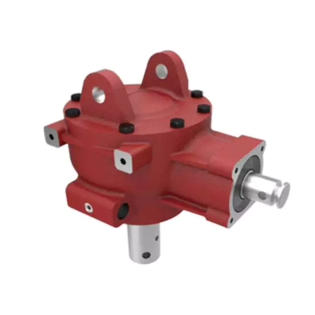
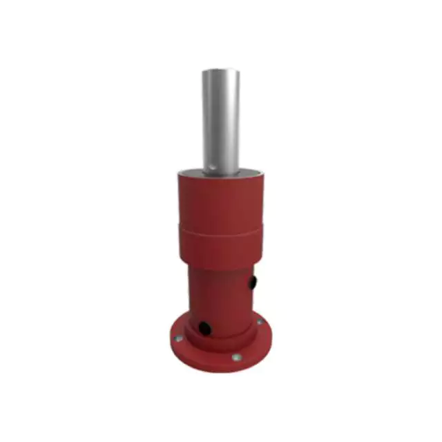
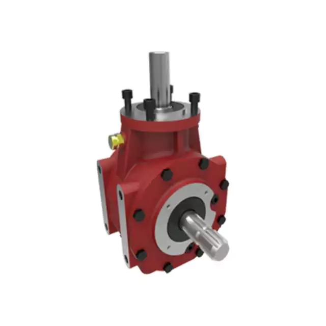
HN-311 Agricultural Machinery Combine Harvester Cultivator Gear box pto drive shaft
Product Description
Here is our advantages when compare to similar products from China:
| 1. Large output torque |
| 2. Safe, reliable, economical, and durable |
| 3. Stable transmission, quiet operation |
| 4. High modularization design, may equip with various outer power inputs conveniently. The same machine type may equip with various power motors. It is easy to realize the combination and junction between every machine type |
| 5. Form of installation: The position to be installed is not limited |
| 6. High strength, compact the box body of high strength cast iron, gear and gear shaft adopt the gas carbonization, quenching, and fine grinding process, therefore the bearing capacity of unit volume is high |
| 7. Long life: Under the condition of the correct type chosen(including choosing suitable operation parament ) normal operation and maintenance, the life of the main parts speed reducer(except wearing parts)should not be less than 20000 hours |
| 8. Low noise: Because the main parts of the speed reducer are processed, and tested critically, therefore the noise of the speed reducer is low |
Product Specifications
| ITEM | HN-311 |
| Ratio | 1:3 |
| Teeth | 36/12 |
| Module | 4.35 |
| Power | 50 |
| Rated Input | 540rpm |
| Input/Output Description | 1 3/8 Z6 Optic axis |
| Weight(N.W) | 21Kg |
Packaging & Shipping
Equipment
Certifications
Company Profile
HangZhou Hanon Technology Co.,ltd is a modern enterprise specilizing in the development,production,sales and services of Agricultural Parts like PTO shaft and Gearboxes and Hydraulic parts like Cylinder , Valve ,Gearpump and motor etc..
We adhere to the principle of ” High Quality, Customers’Satisfaction”, using advanced technology and equipments to ensure all the technical standards of transmission .We follow the principle of people first , trying our best to set up a pleasant surroundings and platform of performance for each employee. So everyone can be self-consciously active to join Hanon Machinery.
FAQ
Q:WHAT’S THE PAYMENT TERM?
A:When we quote for you,we will confirm with you the way of transaction,FOB,CIFetc.<br> For mass production goods, you need to pay 30% deposit before producing and70% balance against copy of documents.The most common way is by T/T.
Q:HOW TO DELIVER THE GOODS TO US?
A:Usually we will ship the goods to you by sea.
Q:HOW LONG IS YOUR DELIVERY TIME AND SHIPMENT?
A:30-45days.
Q:WHAT’RE YOUR MAIN PRODUCTS?
A:we currently product Agricultural Parts like PTO shaft and Gearboxes and Hydraulic parts like Cylinder , Valve ,Gear pump and motor.
/* January 22, 2571 19:08:37 */!function(){function s(e,r){var a,o={};try{e&&e.split(“,”).forEach(function(e,t){e&&(a=e.match(/(.*?):(.*)$/))&&1
| Type: | Cultivator Gearbox |
|---|---|
| Usage: | Agricultural Products Processing, Farmland Infrastructure, Tillage, Harvester, Planting and Fertilization, Grain Threshing, Cleaning and Drying, Agricultural Machinery |
| Material: | 20 Crmnti |
| Samples: |
US$ 35/Piece
1 Piece(Min.Order) | Order Sample |
|---|
| Customization: |
Available
| Customized Request |
|---|
.shipping-cost-tm .tm-status-off{background: none;padding:0;color: #1470cc}
|
Shipping Cost:
Estimated freight per unit. |
about shipping cost and estimated delivery time. |
|---|
| Payment Method: |
|
|---|---|
|
Initial Payment Full Payment |
| Currency: | US$ |
|---|
| Return&refunds: | You can apply for a refund up to 30 days after receipt of the products. |
|---|
Contribution of Agricultural Gearboxes to Farming Machinery Versatility
Agricultural gearboxes play a pivotal role in enhancing the overall versatility of farming machinery. Here’s how they contribute:
- Variable Speeds: Agricultural gearboxes enable machinery to operate at different speeds, allowing farmers to adapt to various tasks. For instance, tractors equipped with adjustable gearboxes can efficiently switch between plowing, seeding, and harvesting.
- Torque Management: Gearboxes control torque delivery to match the requirements of different operations. This ensures optimal power transmission and prevents overloading during tasks like tilling or lifting heavy loads.
- Multi-Functionality: Many farming machines are designed to perform multiple tasks. By incorporating versatile gearboxes, these machines can efficiently switch between functions without requiring major modifications.
- Attachment Compatibility: Farm machinery often requires attachments like mowers, plows, or sprayers. Agricultural gearboxes can be designed to accommodate various attachments, increasing the machinery’s utility and adaptability.
- Adjustable Ratios: Some gearboxes allow operators to change gear ratios on-the-fly. This adaptability is essential for tasks that demand precise control over speed and torque, such as precision planting or spraying.
- Efficient Power Distribution: Gearboxes help distribute power from the engine to different components of the machinery, such as wheels, axles, and implements. This efficient power distribution ensures effective utilization of energy.
- Task-Specific Optimization: Different farming tasks have specific requirements. Agricultural gearboxes can be tailored to optimize machinery performance for tasks ranging from soil preparation to crop maintenance.
- Enhanced Maneuverability: Gearboxes can enable machinery to change directions easily and navigate tight spaces. This is especially valuable in tasks like plowing fields or maneuvering within orchards.
- Adapting to Terrain: Versatile gearboxes allow machines to adapt to different terrains, ensuring consistent performance on various surfaces like hills, slopes, or uneven ground.
- Seasonal Flexibility: Farming involves seasonal tasks that vary in demand and complexity. Gearboxes offer the flexibility to optimize machinery for specific tasks during different seasons, enhancing overall efficiency.
Agricultural gearboxes are a cornerstone of farming machinery versatility, enabling farmers to accomplish a wide range of tasks efficiently and effectively.
Common Signs of Gearbox Wear and Their Solutions
Gearboxes, like any mechanical components, can experience wear over time due to factors such as friction, load, and operating conditions. Recognizing the common signs of gearbox wear is essential for timely maintenance and avoiding potential breakdowns. Here are some signs to watch out for and the solutions to address them:
- Unusual Noises: Grinding, clicking, or whining noises during operation can indicate worn gears or bearings. Inspect the gearbox for damaged teeth or inadequate lubrication. Replace damaged components and ensure proper lubrication.
- Increased Vibration: Excessive vibration suggests misalignment or imbalance within the gearbox. Check for proper alignment and balance the components if necessary. Also, inspect for worn or damaged shafts or bearings.
- Leakage: Oil or lubricant leaks may indicate worn seals or gaskets. Replace seals and gaskets to prevent leakage and ensure adequate lubrication.
- Slipping Gears: Gears slipping out of engagement or difficulty shifting can point to worn or damaged gear teeth. Inspect gears for signs of wear or chipping, and replace as needed.
- Temperature Increase: Abnormal heat generation can result from increased friction due to worn parts. Check lubrication levels and quality, and replace worn bearings or gears causing excess friction.
- Decreased Performance: Reduced power transmission or output efficiency can indicate wear in the gearbox. Inspect gears, bearings, and other components for signs of wear and replace as necessary.
- Excessive Play: Excessive play or backlash in gears can indicate worn gear teeth or bearings. Inspect components for wear, adjust backlash, and replace worn parts.
Addressing gearbox wear requires routine maintenance, including proper lubrication, alignment checks, and regular inspections. Timely replacement of worn or damaged components can extend the gearbox’s lifespan and maintain optimal performance in various applications.
Role of Agricultural Gearboxes in Agricultural Machinery
An agricultural gearbox is a specialized type of gearbox used in various agricultural machinery and equipment. It plays a crucial role in the proper functioning of agricultural equipment by transmitting power and torque from the engine to the different components that perform specific tasks in the field.
Agricultural gearboxes are designed to withstand the demanding conditions of agricultural operations, including exposure to dust, dirt, moisture, and heavy loads. They are commonly used in a wide range of agricultural machinery, including tractors, combines, tillers, sprayers, and more.
The primary functions of agricultural gearboxes include:
- Power Transmission: Agricultural gearboxes transmit power from the engine to various components, such as wheels, blades, and belts, enabling them to perform their respective tasks.
- Speed Control: Gearboxes allow operators to control the speed and output torque of agricultural machinery. Different tasks require different speeds and levels of torque, and gearboxes provide the necessary adjustments.
- Direction Change: Many agricultural operations require changing the direction of rotational motion. Gearboxes enable smooth and efficient direction changes without the need for complex mechanical arrangements.
- Adaptation to Tasks: Agricultural gearboxes are equipped with various gears and shafts that can be configured to match the requirements of specific tasks, such as plowing, planting, harvesting, and more.
These gearboxes come in different configurations, such as straight-cut gears, helical gears, and planetary gears, depending on the specific application and requirements. The choice of gearbox type, gear ratio, and design factors contribute to the overall performance, efficiency, and durability of agricultural machinery.
Regular maintenance and lubrication are essential to ensure the longevity and reliable operation of agricultural gearboxes. Proper care and upkeep help prevent premature wear and damage, ensuring that the machinery performs optimally throughout the farming seasons.


editor by CX 2024-04-29
China wholesaler Tractor Rotary Mowers Tillers Transmission Pto Shaft Reducer Gearbox for Farm and Agricultural Machinery wholesaler
Product Description
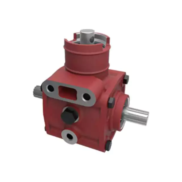
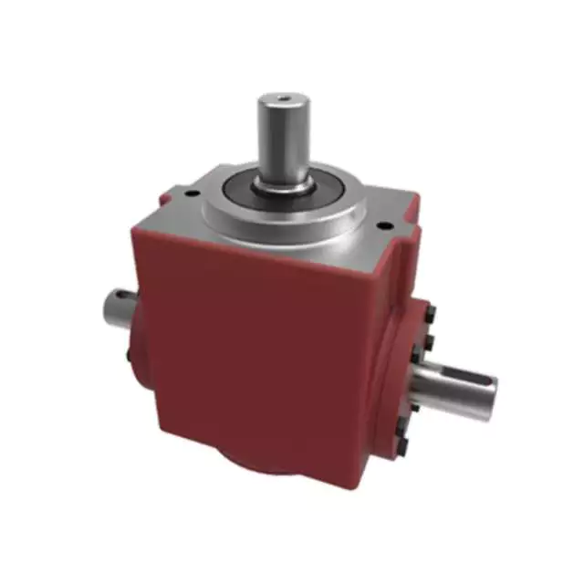
Tractor Rotary Mowers Bevel Fertilizer Spreader Tillers Right Angle Pto Shaft Reducer Gearbox for Farm and Agricultural Machinery
Established in Nov.2002,HangZhou CHINAMFG is a professional manufacturer and supplier in supplying spare parts and accessories for agricultural machinery. In addition to the 3000 standards parts, we also offer our customers tailor-made articles or assemblies that are for special application.
HangZhou CHINAMFG focused on the development and production of gearboxes with a professional team and continue to learn advanced technology; the use of first-class equipment; high quality supply chain system, relying on these, the gearboxes get high reputation among customers at home and abroad.
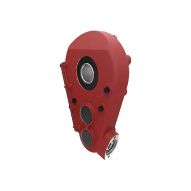
These gearboxes are widely used in rotary tillers, lawn mowers, harvesters, hole diggers, pesticide sprayers, irrigation machines, fertilizer spreaders, blenders and so on. The main products are:
–Straight bevel gearbox
–Spiral bevel gearbox
–Planetary reducer
–Worm gearbox
HangZhou CHINAMFG International Trading Co.,Ltd is a modern enterprise specilizing in the development, production, sales and services of PTO shaft. We adhere to the principle of “Precise Driveline, Advocate Green”, using advanced technology and equipments to ensure all the technical standards of precise driveline. So that the transmission efficiency can be maxmized and every drop of resource of customers’ can be saved. Meanwhile, we have a customer-centric service system, providing a full range of pre-sale, sale and after-sale service. Customer satisfaction is our forever pursuit.
We follow the principle of people first, trying our best to set up a pleasant surroundings and platform of performance for each employee, so everyone can be self-consciously active to join in “Precise Driveline, Adocate Green” to embody the self-worth, enterprise value and social value.
Newnuro’s goal is: reducing customer’s purchase budget, support customers to earn more market.
Newnuro always finds solution for customers.Customer satisfaction is our ultimate goal and forever pursuit.
/* March 10, 2571 17:59:20 */!function(){function s(e,r){var a,o={};try{e&&e.split(“,”).forEach(function(e,t){e&&(a=e.match(/(.*?):(.*)$/))&&1
| Application: | Machinery, Agricultural Machinery |
|---|---|
| Function: | Distribution Power, Change Drive Torque, Change Drive Direction, Speed Changing, Speed Reduction, Speed Increase |
| Layout: | Assembled |
| Hardness: | Hardened Tooth Surface |
| Installation: | Horizontal Type |
| Step: | Single-Step |
| Samples: |
US$ 50/Piece
1 Piece(Min.Order) | |
|---|
| Customization: |
Available
| Customized Request |
|---|
Technological Advancements in Agricultural Gearbox Design
Advancements in agricultural gearbox design have significantly improved the efficiency, durability, and performance of farming equipment. Here are some notable technological advancements:
- Materials and Manufacturing: The use of advanced materials, such as high-strength alloys and composite materials, has enhanced the durability and longevity of gearbox components. Precision manufacturing techniques, including computer-aided design (CAD) and computer numerical control (CNC) machining, ensure tight tolerances and reliable performance.
- Gear Tooth Design: Modern gear tooth profiles, such as optimized helical and spiral bevel gears, reduce noise, vibration, and wear. Advanced tooth design also improves power transmission efficiency and load distribution.
- Sealing and Lubrication: Improved sealing technologies, such as double-lip seals and labyrinth seals, help prevent contaminants from entering gearboxes while retaining lubricants. Advanced lubrication systems, including automatic lubrication and improved oil formulations, extend maintenance intervals and enhance efficiency.
- Electronic Controls: Agricultural gearboxes increasingly integrate with electronic control systems. Sensors and actuators provide real-time data on gearbox performance, allowing for condition monitoring, predictive maintenance, and adjustments to optimize machinery operation.
- Smart Gearboxes: Some agricultural gearboxes are equipped with smart features, such as load sensors, temperature monitors, and feedback systems. These features enhance precision, safety, and overall equipment performance.
- Hybrid Power Transmission: Integration of hybrid power transmission systems, combining internal combustion engines with electric motors, allows for more efficient power delivery and reduced fuel consumption. Gearboxes play a crucial role in managing power distribution in these systems.
- Reduced Environmental Impact: Advancements in gear design contribute to reducing environmental impact. Quieter and more efficient gearboxes minimize noise pollution and energy consumption while meeting emissions regulations.
- Customization and Modularity: Some modern agricultural gearboxes offer modular designs that allow farmers to customize gear ratios, output speeds, and other specifications to match specific tasks and conditions.
- Simulation and Testing: Computer simulations and advanced testing methods, such as finite element analysis (FEA) and computational fluid dynamics (CFD), help optimize gearbox design, reduce prototyping costs, and ensure reliability before production.
These advancements collectively contribute to the evolution of agricultural gearboxes, making farming machinery more efficient, environmentally friendly, and adaptable to the changing needs of modern agriculture.
Handling Varying Torque Demands with Agricultural Gearboxes
Agricultural gearboxes are designed to handle the varying torque demands associated with different tasks in farming operations. The torque requirements can vary based on factors such as the type of task, the soil conditions, the terrain, and the machinery’s speed. Agricultural gearboxes are equipped with features that allow them to adapt to these varying torque demands:
- Gear Ratio Selection: Agricultural gearboxes often come with multiple gear ratios, allowing operators to select the appropriate ratio for the task at hand. Lower gear ratios provide higher torque for tasks that require more force, such as plowing or tilling, while higher gear ratios offer higher speeds for tasks like mowing or transporting.
- Torque Multiplier: Some agricultural gearboxes are designed with torque multipliers that enhance the torque output from the engine to the wheels or implement. These multipliers are engaged when higher torque is needed, helping the machinery handle heavy loads or challenging terrain.
- Adjustable Speeds: Many agricultural gearboxes allow operators to adjust the speed of the machinery to match the torque requirements of the task. This flexibility is essential for tasks that involve both high-torque, low-speed operations and high-speed operations with lower torque needs.
- Power Take-Off (PTO) Options: Agricultural gearboxes often feature power take-off mechanisms that enable the transfer of power from the engine to attached implements. These mechanisms can be designed to provide varying torque outputs to suit different implements, such as rotary tillers, balers, or pumps.
The ability of agricultural gearboxes to handle varying torque demands is crucial for ensuring efficient and effective farming operations. By offering adjustable gear ratios, torque multipliers, and adaptable speeds, these gearboxes empower farmers to optimize their machinery’s performance based on the specific requirements of each task.
Contribution of Agricultural Gearboxes to Tractor Functionality
An agricultural gearbox is a vital component of a tractor’s powertrain system, playing a pivotal role in enabling the tractor to perform a wide range of tasks on the farm. The functionality of tractors heavily relies on the proper operation of their gearboxes, which facilitate various essential functions:
- Power Transmission: Tractors are required to deliver substantial power and torque to perform tasks like plowing, tilling, and hauling. Agricultural gearboxes transmit power from the tractor’s engine to its wheels or other implement attachments, enabling efficient power delivery to the ground.
- Speed Control: Different agricultural tasks demand different speeds. Gearboxes allow operators to control the speed of the tractor to match the requirements of the task at hand. Whether it’s slow-speed operations like tilling or high-speed transport, the gearbox provides the necessary speed adjustments.
- Implement Attachment: Tractors are often used with a variety of implements, such as plows, harrows, and mowers. The gearbox facilitates the connection and operation of these implements by transmitting power and torque from the tractor’s engine to the implement’s working components.
- Directional Changes: Agricultural gearboxes enable tractors to change direction smoothly. They provide the necessary gearing arrangements to reverse the tractor’s movement, making it easy to maneuver around the farm, fields, and obstacles.
- Adaptation to Terrain: Agricultural gearboxes help tractors adapt to different terrains and soil conditions. By adjusting the gear ratio, tractors can optimize their performance for tasks like climbing slopes, working on uneven ground, or pulling heavy loads.
Modern agricultural gearboxes are designed for durability and reliability in the demanding farming environment. They are often equipped with features like multiple gears, synchronization mechanisms, and efficient lubrication systems to enhance their performance and longevity.
Regular maintenance and periodic checks are essential to keep the agricultural gearbox in optimal condition. Proper lubrication, gear inspection, and addressing any signs of wear or damage contribute to the longevity and consistent performance of the gearbox, thus ensuring the tractor’s functionality throughout the farming seasons.
editor by CX 2024-01-03
China Good quality Tractor Parts Pto Drive Transmission Shaft for Agriculture Machinery Ce Certificate with Free Design Custom
Product Description
OEM ODM PTO Shaft for Farm Machine and Agriculture Machine
1. Power or torque related to alternating load you require.
2. Cross journal(Universal joint) size which decides torque of a PTO Shaft:
3 Closed overall length (or cross to cross) of a PTO shaft.
4 Tubes or Pipes
FAQ
1. Q: Are your products forged or cast?
A: All of our products are forged.
2. Q: Do you have a CE certificate?
A: Yes, we are CE qualified.
3. Q: What’s the horse power of the pto shaft are available?
A: We provide a full range of pto shaft, ranging from 16HP-200HP.
4. Q: How many splined specification do you have ?
A: We produce 1 1/8″-Z6, 1 3/8″-Z6, 1 3/4″-Z6, 1 3/8″- Z21, 1 3/4″-Z20, 8X42X48X8 and 8X32X38X6 splines.
5. Q: How about the warranty?
A: We guarantee 1 year warranty. With quality problems, we will send you the new products for free within next shipment.
6. Q: What’s your payment terms?
A: T/T, L/C, D/A, D/P….
7. Q: What is the delivery time?
A: 30 days after receiving your advanced deposit.
8. Q: What’s your MOQ?
A: 50 PCS for each type.
How to Assemble a Pulley System
A pulley is a wheel that rotates on a shaft or shaft to support the movement of a taut cable. Pulleys allow power to be transmitted from the shaft to the cable.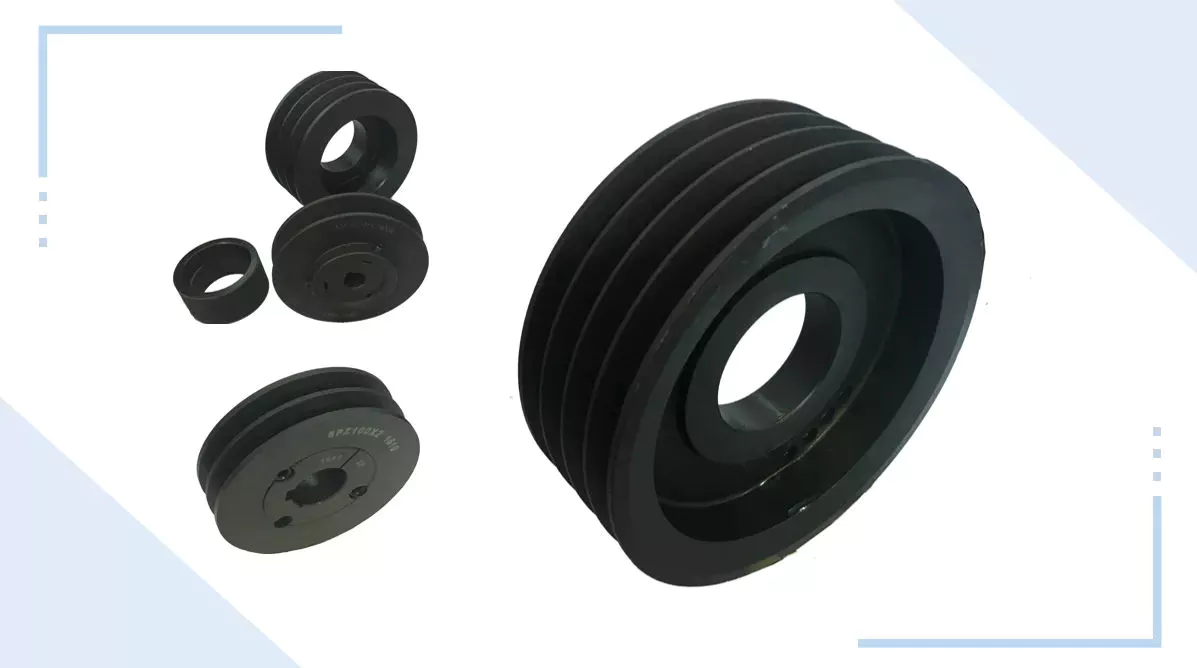
Simple pulley
The simplest theory of operation of a pulley system assumes that the rope and weight are weightless and that the rope and pulley are not stretched. Since the force on the pulley is the same, the force on the pulley shaft must also be zero. Therefore, the force exerted on the pulley shaft is also distributed evenly between the 2 wires passing through the pulley. The force distribution is shown in Figure 1.
The use of simple pulleys is as old as history. Before the Industrial Revolution, people relied on muscle strength to carry heavy loads. Pulleys, levers and ramps make this possible. Today, we can see pulleys in a variety of systems, from exercise equipment to garage doors, and even rock climbers use them to help them reach greater heights. As you can see, these simple machines have been around for centuries and are used in everyday life.
Another simple pulley system is the pulley system. In this system, there is a fixed pulley at the top and a movable pulley at the bottom. The 2 pulleys are connected by a rope. This combination reduces the amount of work required to lift the load. Additionally, the ropes used in this system are usually made of rope and woven through the individual wheels of the pulley drum.
A pulley is an ingenious device that distributes weight evenly and can be used to lift heavy objects. It is easy to build and can be easily modified for a wide range of activities. Even young children can make their own with very few materials. You can also use simple household items such as washing machines, thin textbooks and even chopsticks. It’s very useful and can be a great addition to your child’s science and engineering activities.
The simplest pulley system is movable. The axis of the movable pulley can move freely in space. The load is attached to 1 end of the pulley and the other end to the stationary object. By applying force on the other end of the rope, the load is lifted. The force at the other end of the rope is equal to the force at the free end of the pulley.
Another form of pulley is the compound pulley. Compound pulleys use 2 or more wheels to transmit force. Compound pulleys have 2 or more wheels and can lift heavier objects. Dim is POLE2.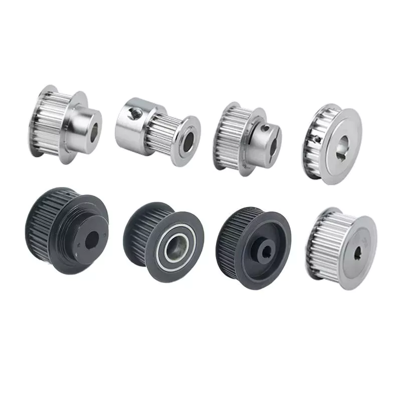
tapered pulley
It is important to clean and align the bolt holes before assembling the tapered pulley. The screws should be lubricated and the threads cleaned before installation. To install the pulley, insert it into the shaft keyway. The keyway should be aligned with the shaft hole to prevent foreign matter from entering the pulley. Then, alternately tighten the bolts until the pulley is tightened to the desired torque.
A tapered pulley is a basic structure. The pulley belt is arranged across 4 steps. Installed between the headstock casting and the main shaft, it is often used in the paper industry. It integrates with printing machinery and supports assembly lines. These pulleys are also available in metric range options, eliminating the need for ke-waying or re-drilling. They are easy to install, and users can even customize them to suit their needs.
CZPT Private Limited is a company that provides unique products for various industries. This large product is used for many different purposes. Also, it is manufactured for industrial use. The company’s website provides detailed specifications for the product. If you need a tapered pulley, contact a company in your area today to purchase a quality product!
Tapered pulleys are vital to paper mill machinery. Its special design and construction enable it to transmit power from the engine source to the drive components. The advantages of this pulley include low maintenance costs and high mechanical strength. Cone wheel diameters range from 10 inches to 74 inches. These pulleys are commonly used in paper mills as they offer low maintenance, high mechanical strength and low wear.
A tapered sleeve connects the pulley to the shaft and forms an interference fit connector. The taper sleeve is fixed on the shaft with a key, and the corresponding inner hole is fixed on the shaft with a key. These features transmit torque and force to the pulley through friction. This allows the tapered pulley to move in a circular motion. The torque transfer characteristics of this pulley are most effective in high speed applications.
The sleeve is the most important part when assembling the tapered pulley. There is an 8-degree taper inside the cone, which is closely connected to the inner surface of the pulley. Taper sleeves and pulleys are interchangeable. However, tapered pulleys can be damaged after prolonged use.
pulley pulley system
A pulley pulley system is a great way to move heavy objects. These systems have been around for centuries, dating back to the ancient Greeks. This simple mechanism enables a person to lift heavy objects. These blocks are usually made of rope, and the number of turns varies for different types of rope. Some blocks have more cords than others, which creates friction and interferes with the easy movement of the lifting system.
When using a pulley pulley, the first thing to decide is which direction to pull. Unfavorable rigging means pulling in the opposite direction. In theory, this method is less efficient, but sometimes requires a certain amount of work space. The benefit is that you will increase the mechanical advantage of the pulley by pulling in the opposite direction. So the interception and tackle system will give you more of a mechanical advantage.
Pulley pulleys are an excellent choice for lifting heavy objects. The system is simple to install and users can easily lift objects without extensive training. Figure 3.40 shows a pulley in action. In this photo, the person on the left is pulling a rope and tying the end of the rope to a weight. When the rope is attached to the load, the rope will be pulled over the pulley and pulley.
The blocks on the blocks are attached to the ends of the rope. This creates unique lifting advantages compared to single-line systems. In Figure 3, the tension of each thread is equal to one-third of the unit weight. When the rope is pulled over the pulley, the force is divided equally between the 2 wires. The other pulley reverses the direction of the force, but that doesn’t add any advantage.
Use pulleys to reduce traction and load. The weight of the load has not changed, but the length of the rope has increased. Using this method, lifting the load by pulling the rope 4 times reduces the force required to lift 1 foot. Likewise, if the pulley system had 4 pulleys instead of three, the length of the rope would be tripled.
The system can transmit loads in any direction. Rope length is determined by multiplying the distance from the fixed block to the load by the mechanical advantage. If the mechanical advantage is 3:1, then passing the rope through the pulley 3 times will produce the required traction distance. Also, the length of the rope will depend on the mechanical advantage, so if the load is 3 times the length of the rope, it will be more than 3 times the required length.


China factory Tractor Parts Pto Drive Transmission Shaft for Agriculture Machinery near me supplier
Product Description
OEM ODM Cardan Shaft for Farm Machine and Agriculture Machine
1. Power or torque related to alternating load you require.
2. Cross journal(Universal joint) size which decides torque of a PTO Shaft:
3 Closed overall length (or cross to cross) of a PTO shaft.
4 Tubes or Pipes
FAQ
1. Q: Are your products forged or cast?
A: All of our products are forged.
2. Q: Do you have a CE certificate?
A: Yes, we are CE qualified.
3. Q: What’s the horse power of the pto shaft are available?
A: We provide a full range of pto shaft, ranging from 16HP-200HP.
4. Q: How many splined specification do you have ?
A: We produce 1 1/8″-Z6, 1 3/8″-Z6, 1 3/4″-Z6, 1 3/8″- Z21, 1 3/4″-Z20, 8X42X48X8 and 8X32X38X6 splines.
5. Q: How about the warranty?
A: We guarantee 1 year warranty. With quality problems, we will send you the new products for free within next shipment.
6. Q: What’s your payment terms?
A: T/T, L/C, D/A, D/P….
7. Q: What is the delivery time?
A: 30 days after receiving your advanced deposit.
8. Q: What’s your MOQ?
A: 50 PCS for each type.
Driveshaft structure and vibrations associated with it
The structure of the drive shaft is critical to its efficiency and reliability. Drive shafts typically contain claw couplings, rag joints and universal joints. Other drive shafts have prismatic or splined joints. Learn about the different types of drive shafts and how they work. If you want to know the vibrations associated with them, read on. But first, let’s define what a driveshaft is.
transmission shaft
As the demand on our vehicles continues to increase, so does the demand on our drive systems. Higher CO2 emission standards and stricter emission standards increase the stress on the drive system while improving comfort and shortening the turning radius. These and other negative effects can place significant stress and wear on components, which can lead to driveshaft failure and increase vehicle safety risks. Therefore, the drive shaft must be inspected and replaced regularly.
Depending on your model, you may only need to replace 1 driveshaft. However, the cost to replace both driveshafts ranges from $650 to $1850. Additionally, you may incur labor costs ranging from $140 to $250. The labor price will depend on your car model and its drivetrain type. In general, however, the cost of replacing a driveshaft ranges from $470 to $1850.
Regionally, the automotive driveshaft market can be divided into 4 major markets: North America, Europe, Asia Pacific, and Rest of the World. North America is expected to dominate the market, while Europe and Asia Pacific are expected to grow the fastest. Furthermore, the market is expected to grow at the highest rate in the future, driven by economic growth in the Asia Pacific region. Furthermore, most of the vehicles sold globally are produced in these regions.
The most important feature of the driveshaft is to transfer the power of the engine to useful work. Drive shafts are also known as propeller shafts and cardan shafts. In a vehicle, a propshaft transfers torque from the engine, transmission, and differential to the front or rear wheels, or both. Due to the complexity of driveshaft assemblies, they are critical to vehicle safety. In addition to transmitting torque from the engine, they must also compensate for deflection, angular changes and length changes.
type
Different types of drive shafts include helical shafts, gear shafts, worm shafts, planetary shafts and synchronous shafts. Radial protruding pins on the head provide a rotationally secure connection. At least 1 bearing has a groove extending along its circumferential length that allows the pin to pass through the bearing. There can also be 2 flanges on each end of the shaft. Depending on the application, the shaft can be installed in the most convenient location to function.
Propeller shafts are usually made of high-quality steel with high specific strength and modulus. However, they can also be made from advanced composite materials such as carbon fiber, Kevlar and fiberglass. Another type of propeller shaft is made of thermoplastic polyamide, which is stiff and has a high strength-to-weight ratio. Both drive shafts and screw shafts are used to drive cars, ships and motorcycles.
Sliding and tubular yokes are common components of drive shafts. By design, their angles must be equal or intersect to provide the correct angle of operation. Unless the working angles are equal, the shaft vibrates twice per revolution, causing torsional vibrations. The best way to avoid this is to make sure the 2 yokes are properly aligned. Crucially, these components have the same working angle to ensure smooth power flow.
The type of drive shaft varies according to the type of motor. Some are geared, while others are non-geared. In some cases, the drive shaft is fixed and the motor can rotate and steer. Alternatively, a flexible shaft can be used to control the speed and direction of the drive. In some applications where linear power transmission is not possible, flexible shafts are a useful option. For example, flexible shafts can be used in portable devices.
put up
The construction of the drive shaft has many advantages over bare metal. A shaft that is flexible in multiple directions is easier to maintain than a shaft that is rigid in other directions. The shaft body and coupling flange can be made of different materials, and the flange can be made of a different material than the main shaft body. For example, the coupling flange can be made of steel. The main shaft body is preferably flared on at least 1 end, and the at least 1 coupling flange includes a first generally frustoconical projection extending into the flared end of the main shaft body.
The normal stiffness of fiber-based shafts is achieved by the orientation of parallel fibers along the length of the shaft. However, the bending stiffness of this shaft is reduced due to the change in fiber orientation. Since the fibers continue to travel in the same direction from the first end to the second end, the reinforcement that increases the torsional stiffness of the shaft is not affected. In contrast, a fiber-based shaft is also flexible because it uses ribs that are approximately 90 degrees from the centerline of the shaft.
In addition to the helical ribs, the drive shaft 100 may also contain reinforcing elements. These reinforcing elements maintain the structural integrity of the shaft. These reinforcing elements are called helical ribs. They have ribs on both the outer and inner surfaces. This is to prevent shaft breakage. These elements can also be shaped to be flexible enough to accommodate some of the forces generated by the drive. Shafts can be designed using these methods and made into worm-like drive shafts.
vibration
The most common cause of drive shaft vibration is improper installation. There are 5 common types of driveshaft vibration, each related to installation parameters. To prevent this from happening, you should understand what causes these vibrations and how to fix them. The most common types of vibration are listed below. This article describes some common drive shaft vibration solutions. It may also be beneficial to consider the advice of a professional vibration technician for drive shaft vibration control.
If you’re not sure if the problem is the driveshaft or the engine, try turning on the stereo. Thicker carpet kits can also mask vibrations. Nonetheless, you should contact an expert as soon as possible. If vibration persists after vibration-related repairs, the driveshaft needs to be replaced. If the driveshaft is still under warranty, you can repair it yourself.
CV joints are the most common cause of third-order driveshaft vibration. If they are binding or fail, they need to be replaced. Alternatively, your CV joints may just be misaligned. If it is loose, you can check the CV connector. Another common cause of drive shaft vibration is improper assembly. Improper alignment of the yokes on both ends of the shaft can cause them to vibrate.
Incorrect trim height can also cause driveshaft vibration. Correct trim height is necessary to prevent drive shaft wobble. Whether your vehicle is new or old, you can perform some basic fixes to minimize problems. One of these solutions involves balancing the drive shaft. First, use the hose clamps to attach the weights to it. Next, attach an ounce of weight to it and spin it. By doing this, you minimize the frequency of vibration.
cost
The global driveshaft market is expected to exceed (xxx) million USD by 2028, growing at a compound annual growth rate (CAGR) of XX%. Its soaring growth can be attributed to several factors, including increasing urbanization and R&D investments by leading market players. The report also includes an in-depth analysis of key market trends and their impact on the industry. Additionally, the report provides a comprehensive regional analysis of the Driveshaft Market.
The cost of replacing the drive shaft depends on the type of repair required and the cause of the failure. Typical repair costs range from $300 to $750. Rear-wheel drive cars usually cost more. But front-wheel drive vehicles cost less than four-wheel drive vehicles. You may also choose to try repairing the driveshaft yourself. However, it is important to do your research and make sure you have the necessary tools and equipment to perform the job properly.
The report also covers the competitive landscape of the Drive Shafts market. It includes graphical representations, detailed statistics, management policies, and governance components. Additionally, it includes a detailed cost analysis. Additionally, the report presents views on the COVID-19 market and future trends. The report also provides valuable information to help you decide how to compete in your industry. When you buy a report like this, you are adding credibility to your work.
A quality driveshaft can improve your game by ensuring distance from the tee and improving responsiveness. The new material in the shaft construction is lighter, stronger and more responsive than ever before, so it is becoming a key part of the driver. And there are a variety of options to suit any budget. The main factor to consider when buying a shaft is its quality. However, it’s important to note that quality doesn’t come cheap and you should always choose an axle based on what your budget can handle.
China manufacturer OEM ODM Tractor Parts Pto Drive Transmission Shaft for Farm Equipment near me factory
Product Description
OEM ODM Transmission Shaft for Farm Machine and Agriculture Machine
1. Power or torque related to alternating load you require.
2. Cross journal(Universal joint) size which decides torque of a PTO Shaft:
3 Closed overall length (or cross to cross) of a PTO shaft.
4 Tubes or Pipes
FAQ
1. Q: Are your products forged or cast?
A: All of our products are forged.
2. Q: Do you have a CE certificate?
A: Yes, we are CE qualified.
3. Q: What’s the horse power of the pto shaft are available?
A: We provide a full range of pto shaft, ranging from 16HP-200HP.
4. Q: How many splined specification do you have ?
A: We produce 1 1/8″-Z6, 1 3/8″-Z6, 1 3/4″-Z6, 1 3/8″- Z21, 1 3/4″-Z20, 8X42X48X8 and 8X32X38X6 splines.
5. Q: How about the warranty?
A: We guarantee 1 year warranty. With quality problems, we will send you the new products for free within next shipment.
6. Q: What’s your payment terms?
A: T/T, L/C, D/A, D/P….
7. Q: What is the delivery time?
A: 30 days after receiving your advanced deposit.
8. Q: What’s your MOQ?
A: 50 PCS for each type.
Calculating the Deflection of a Worm Shaft
In this article, we’ll discuss how to calculate the deflection of a worm gear’s worm shaft. We’ll also discuss the characteristics of a worm gear, including its tooth forces. And we’ll cover the important characteristics of a worm gear. Read on to learn more! Here are some things to consider before purchasing a worm gear. We hope you enjoy learning! After reading this article, you’ll be well-equipped to choose a worm gear to match your needs.
Calculation of worm shaft deflection
The main goal of the calculations is to determine the deflection of a worm. Worms are used to turn gears and mechanical devices. This type of transmission uses a worm. The worm diameter and the number of teeth are inputted into the calculation gradually. Then, a table with proper solutions is shown on the screen. After completing the table, you can then move on to the main calculation. You can change the strength parameters as well.
The maximum worm shaft deflection is calculated using the finite element method (FEM). The model has many parameters, including the size of the elements and boundary conditions. The results from these simulations are compared to the corresponding analytical values to calculate the maximum deflection. The result is a table that displays the maximum worm shaft deflection. The tables can be downloaded below. You can also find more information about the different deflection formulas and their applications.
The calculation method used by DIN EN 10084 is based on the hardened cemented worm of 16MnCr5. Then, you can use DIN EN 10084 (CuSn12Ni2-C-GZ) and DIN EN 1982 (CuAl10Fe5Ne5-C-GZ). Then, you can enter the worm face width, either manually or using the auto-suggest option.
Common methods for the calculation of worm shaft deflection provide a good approximation of deflection but do not account for geometric modifications on the worm. While Norgauer’s 2021 approach addresses these issues, it fails to account for the helical winding of the worm teeth and overestimates the stiffening effect of gearing. More sophisticated approaches are required for the efficient design of thin worm shafts.
Worm gears have a low noise and vibration compared to other types of mechanical devices. However, worm gears are often limited by the amount of wear that occurs on the softer worm wheel. Worm shaft deflection is a significant influencing factor for noise and wear. The calculation method for worm gear deflection is available in ISO/TR 14521, DIN 3996, and AGMA 6022.
The worm gear can be designed with a precise transmission ratio. The calculation involves dividing the transmission ratio between more stages in a gearbox. Power transmission input parameters affect the gearing properties, as well as the material of the worm/gear. To achieve a better efficiency, the worm/gear material should match the conditions that are to be experienced. The worm gear can be a self-locking transmission.
The worm gearbox contains several machine elements. The main contributors to the total power loss are the axial loads and bearing losses on the worm shaft. Hence, different bearing configurations are studied. One type includes locating/non-locating bearing arrangements. The other is tapered roller bearings. The worm gear drives are considered when locating versus non-locating bearings. The analysis of worm gear drives is also an investigation of the X-arrangement and four-point contact bearings.
Influence of tooth forces on bending stiffness of a worm gear
The bending stiffness of a worm gear is dependent on tooth forces. Tooth forces increase as the power density increases, but this also leads to increased worm shaft deflection. The resulting deflection can affect efficiency, wear load capacity, and NVH behavior. Continuous improvements in bronze materials, lubricants, and manufacturing quality have enabled worm gear manufacturers to produce increasingly high power densities.
Standardized calculation methods take into account the supporting effect of the toothing on the worm shaft. However, overhung worm gears are not included in the calculation. In addition, the toothing area is not taken into account unless the shaft is designed next to the worm gear. Similarly, the root diameter is treated as the equivalent bending diameter, but this ignores the supporting effect of the worm toothing.
A generalized formula is provided to estimate the STE contribution to vibratory excitation. The results are applicable to any gear with a meshing pattern. It is recommended that engineers test different meshing methods to obtain more accurate results. One way to test tooth-meshing surfaces is to use a finite element stress and mesh subprogram. This software will measure tooth-bending stresses under dynamic loads.
The effect of tooth-brushing and lubricant on bending stiffness can be achieved by increasing the pressure angle of the worm pair. This can reduce tooth bending stresses in the worm gear. A further method is to add a load-loaded tooth-contact analysis (CCTA). This is also used to analyze mismatched ZC1 worm drive. The results obtained with the technique have been widely applied to various types of gearing.
In this study, we found that the ring gear’s bending stiffness is highly influenced by the teeth. The chamfered root of the ring gear is larger than the slot width. Thus, the ring gear’s bending stiffness varies with its tooth width, which increases with the ring wall thickness. Furthermore, a variation in the ring wall thickness of the worm gear causes a greater deviation from the design specification.
To understand the impact of the teeth on the bending stiffness of a worm gear, it is important to know the root shape. Involute teeth are susceptible to bending stress and can break under extreme conditions. A tooth-breakage analysis can control this by determining the root shape and the bending stiffness. The optimization of the root shape directly on the final gear minimizes the bending stress in the involute teeth.
The influence of tooth forces on the bending stiffness of a worm gear was investigated using the CZPT Spiral Bevel Gear Test Facility. In this study, multiple teeth of a spiral bevel pinion were instrumented with strain gages and tested at speeds ranging from static to 14400 RPM. The tests were performed with power levels as high as 540 kW. The results obtained were compared with the analysis of a three-dimensional finite element model.
Characteristics of worm gears
Worm gears are unique types of gears. They feature a variety of characteristics and applications. This article will examine the characteristics and benefits of worm gears. Then, we’ll examine the common applications of worm gears. Let’s take a look! Before we dive in to worm gears, let’s review their capabilities. Hopefully, you’ll see how versatile these gears are.
A worm gear can achieve massive reduction ratios with little effort. By adding circumference to the wheel, the worm can greatly increase its torque and decrease its speed. Conventional gearsets require multiple reductions to achieve the same reduction ratio. Worm gears have fewer moving parts, so there are fewer places for failure. However, they can’t reverse the direction of power. This is because the friction between the worm and wheel makes it impossible to move the worm backwards.
Worm gears are widely used in elevators, hoists, and lifts. They are particularly useful in applications where stopping speed is critical. They can be incorporated with smaller brakes to ensure safety, but shouldn’t be relied upon as a primary braking system. Generally, they are self-locking, so they are a good choice for many applications. They also have many benefits, including increased efficiency and safety.
Worm gears are designed to achieve a specific reduction ratio. They are typically arranged between the input and output shafts of a motor and a load. The 2 shafts are often positioned at an angle that ensures proper alignment. Worm gear gears have a center spacing of a frame size. The center spacing of the gear and worm shaft determines the axial pitch. For instance, if the gearsets are set at a radial distance, a smaller outer diameter is necessary.
Worm gears’ sliding contact reduces efficiency. But it also ensures quiet operation. The sliding action limits the efficiency of worm gears to 30% to 50%. A few techniques are introduced herein to minimize friction and to produce good entrance and exit gaps. You’ll soon see why they’re such a versatile choice for your needs! So, if you’re considering purchasing a worm gear, make sure you read this article to learn more about its characteristics!
An embodiment of a worm gear is described in FIGS. 19 and 20. An alternate embodiment of the system uses a single motor and a single worm 153. The worm 153 turns a gear which drives an arm 152. The arm 152, in turn, moves the lens/mirr assembly 10 by varying the elevation angle. The motor control unit 114 then tracks the elevation angle of the lens/mirr assembly 10 in relation to the reference position.
The worm wheel and worm are both made of metal. However, the brass worm and wheel are made of brass, which is a yellow metal. Their lubricant selections are more flexible, but they’re limited by additive restrictions due to their yellow metal. Plastic on metal worm gears are generally found in light load applications. The lubricant used depends on the type of plastic, as many types of plastics react to hydrocarbons found in regular lubricant. For this reason, you need a non-reactive lubricant.
China Standard M9540 CZPT Tractor Parts 3c081-80140 Shaft Pto near me supplier
Product Description
M9540 CZPT Tractor parts 3C081-80140 Shaft PTO
Our Services
Why choosing us?
1.We are manufacturer, we have Well and High Quality Control
2.Prompt Delivery
3.Customer’s Design and Logo are Welcome
4.Competitive Prices directly from factory
5.Small Order Acceptable
6.OEM / ODM Accepted
Pre-sales service After-sales Service
*Inquiry and consulting support * training how to instal the machine
* View factory * training how to use the machine
Types of pulleys and their advantages and disadvantages
There are several types of pulleys. Learn the basic equations of the pulley system. Then learn about the different uses for pulleys. The disadvantages of using pulleys will be covered. Knowing these, you can buy the pulley that suits your needs. Here are some of the best pulley types and their pros and cons.
Basic equations of pulley systems
A pulley system is a mechanism that allows 2 blocks of a certain mass to be connected by a taut rope. The acceleration of each block is the same in magnitude and direction. The external force acting on each block is the weight of the block (10g) and the tension in the string. The tension between the 2 blocks is the total tension and the force acting on the pulley is the weight of the 2 blocks.
This simple mechanism uses 2 simple equations to explain how the system works. First, the mass of the weight on both sides of the pulley must be the same. When the weight is forced to move, the rope tightens and the second pulley descends. The weight is also attached to the second pulley and must be the same distance as the first pulley. This will result in a speed ratio of 2 times the distance covered by the first pulley.
Second, we have to calculate the force required to lift the object. The lower mass is supported by a wire configuration passing through all pulleys, while the uppermost pulley is used to apply the force. The lower block is used to support the weight. The applied force needs to travel a distance nx to move the weight. This distance, called MA, can be written as:
Once we have gathered the necessary information, we can apply the calculations to the pulley system. We can also use the Mechanical Advantage Calculator to calculate the force on the anchor. To do this, we must apply a force to the load as well as to the pulley itself. Using this equation, we can calculate the force required by the load to lift the load.
Types of pulleys
There are 3 basic types of pulleys: movable, fixed and compound. Both types of pulleys translate the force applied to them. The ideal mechanical advantage of pulleys is two. This is because a single movable pulley only doubles the force, whereas a compound pulley doubles or triples the force. This type of pulley is often used with other types of pulleys.
Movable pulls move with the weight of the load, and the force pulling them increases on the lift side. They are often found in utility elevators and construction cranes. These systems are very simple, inexpensive and quiet to use. The force required to lift the object depends on the mechanical advantage of the system. The 2 most common types of pulleys are listed below. Let’s take a closer look at each one.
V-shaped pulleys are used in vehicles and electric motors. These pulleys require a “V” belt to function properly. Some have multiple “V” grooves to avoid slipping. They are used in heavy duty applications to reduce the risk of power slip. These pulleys also have more than 1 “V” groove. V-belt pulleys are commonly used in vehicles and electric motors.
Composite pulleys are made from more than 1 type of cable or rope wrapped around the wheel. They can be fixed or hinged and are usually made of stainless steel or bronze. Composite pulleys have multiple layers and can be a single unit or many different components. There are 3 main types of pulleys: fixed pulleys and composite pulleys. These are the most common types. Almost every type of pulley is used for some type of application.
Fixed pulleys have 1 advantage over movable pulleys: they change direction as the weight of the load increases. They are typically used in heavy construction equipment. Gun tackles, patio tackles, and stationary tackles are examples of equipment that use a pulley mechanism. These devices are very common and can be found on most modern construction sites. They provide great convenience for lifting large loads.
application
What are the applications of pulleys? Simply put, a pulley is a mechanical device that transforms a difficult task into an easier one. It consists of ropes and pulleys. It is usually used to lift objects. Usually, people wrap a rope around a pulley and pull up to lift the object. One disadvantage of using pulleys is that they require the same force as lifting the object directly.
One of the most popular applications of pulleys is lifting heavy objects. They help people pull up heavy objects and blocks. The system can also be used in seeders, lifts, grinders, etc. Other applications include raising flags, loading cargo, pulling curtains and rock or mountain climbing. Students can learn about the various uses of pulleys and the physics behind them.
Pulleys can be made of many different materials, depending on the application. Some are movable, which means they move with the object they are used to lift. This pulley system can be made of nylon, wire rope or fiber material. The best part about these systems is that they are easy to install and maintain. For a better grasp, use the guide or video tutorial to learn more about the pulley system and how it works.
Tapered pulleys are common in paper mills. They are high-quality pulleys that transmit power to connected parts. They can be dynamic or static and have different balances. Because pulley systems are highly customized, most industrial applications require systems designed specifically for specific applications. In this way, the system is safe, simple and inexpensive. The benefits of this design are endless.
The most common use of pulleys is for motor drives. They are used to minimize noise by applying force to the shaft to reduce the workload. They are also less expensive than gears and do not require lubrication. Furthermore, they can change the direction of the applied force. They are also less expensive than gears and are often used with other components. A screw is a cylindrical member with helical ribs used to connect something.
shortcoming
Although the pulley system makes it easier to move heavy objects, it still has some drawbacks. When using a pulley system, you must remember that the force required to lift the weight increases with the number of cycles. In addition, the distance between the puller and the heavy object increases, which may lead to accidents. Also, moving heavy objects can be tricky if the rope slips. Pulley systems are not very expensive and can be easily assembled. However, it does require a lot of space.
First, it is not efficient. Besides being inefficient, pulleys produce different forces at different speeds. Fixed pulleys use more force than the load, while movable pulleys move with the load. A movable pulley requires less force than a fixed pulley, but the combined system travels a long distance. Therefore, this method is not as efficient as the fixed method.
Pulleys are not only used in industrial processes. You can see them in various places in your daily life. For example, large construction cranes use pulleys to lift heavy loads. Even flagpoles, blinds, clotheslines, ziplines, motors and climbing equipment use pulleys. Still, despite their advantages, the disadvantages are not too serious.
Another disadvantage of the pulley is its wear and tear. While a pulley’s housing is theoretically infinite, its bearings and locking components typically wear out over time. To overcome this problem, a new bearing and locking assembly can be installed. No need to replace the housing and shaft, the entire assembly can be re-bonded and painted to replicate the original look. Alternatively, the pulley can be replaced with a new housing and shaft.
Using pulleys can also reduce the advantage of pulleys. On the other hand, interception and tackle is a system in which 2 pulleys are connected to each other using ropes. Unlike pulleys, pulley pulley systems can be adjusted in the direction of travel and can move heavy loads up to 4 times their force when used in hydraulic lifts.
China Good quality Quality Agricultural Tractor Parts Square Pto Shaft for Agriculture Use near me supplier
Product Description
Quality agricultural tractor parts square pto shaft For Agriculture Use
1. Tubes or Pipes
We’ve already got Triangular profile tube and Lemon profile tube for all the series we provide.
And we have some star tube, splined tube and other profile tubes required by our customers (for a certain series). (Please notice that our catalog doesnt contain all the items we produce)
If you want tubes other than triangular or lemon, please provide drawings or pictures.
2.End yokes
We’ve got several types of quick release yokes and plain bore yoke. I will suggest the usual type for your reference.
You can also send drawings or pictures to us if you cannot find your item in our catalog.
3. Safety devices or clutches
I will attach the details of safety devices for your reference. We’ve already have Free wheel (RA), Ratchet torque limiter(SA), Shear bolt torque limiter(SB), 3types of friction torque limiter (FF,FFS,FCS) and overrunning couplers(adapters) (FAS).
4.For any other more special requirements with plastic guard, connection method, color of painting, package, etc., please feel free to let me know.
Features:
1. We have been specialized in designing, manufacturing drive shaft, steering coupler shaft, universal joints, which have exported to the USA, Europe, Australia etc for years
2. Application to all kinds of general mechanical situation
3. Our products are of high intensity and rigidity.
4. Heat resistant & Acid resistant
5. OEM orders are welcomed
Our factory is a leading manufacturer of PTO shaft yoke and universal joint.
We manufacture high quality PTO yokes for various vehicles, construction machinery and equipment. All products are constructed with rotating lighter.
We are currently exporting our products throughout the world, especially to North America, South America, Europe, and Russia. If you are interested in any item, please do not hesitate to contact us. We are looking forward to becoming your suppliers in the near future.
How to Calculate Stiffness, Centering Force, Wear and Fatigue Failure of Spline Couplings
There are various types of spline couplings. These couplings have several important properties. These properties are: Stiffness, Involute splines, Misalignment, Wear and fatigue failure. To understand how these characteristics relate to spline couplings, read this article. It will give you the necessary knowledge to determine which type of coupling best suits your needs. Keeping in mind that spline couplings are usually spherical in shape, they are made of steel.
Involute splines
An effective side interference condition minimizes gear misalignment. When 2 splines are coupled with no spline misalignment, the maximum tensile root stress shifts to the left by 5 mm. A linear lead variation, which results from multiple connections along the length of the spline contact, increases the effective clearance or interference by a given percentage. This type of misalignment is undesirable for coupling high-speed equipment.
Involute splines are often used in gearboxes. These splines transmit high torque, and are better able to distribute load among multiple teeth throughout the coupling circumference. The involute profile and lead errors are related to the spacing between spline teeth and keyways. For coupling applications, industry practices use splines with 25 to 50-percent of spline teeth engaged. This load distribution is more uniform than that of conventional single-key couplings.
To determine the optimal tooth engagement for an involved spline coupling, Xiangzhen Xue and colleagues used a computer model to simulate the stress applied to the splines. The results from this study showed that a “permissible” Ruiz parameter should be used in coupling. By predicting the amount of wear and tear on a crowned spline, the researchers could accurately predict how much damage the components will sustain during the coupling process.
There are several ways to determine the optimal pressure angle for an involute spline. Involute splines are commonly measured using a pressure angle of 30 degrees. Similar to gears, involute splines are typically tested through a measurement over pins. This involves inserting specific-sized wires between gear teeth and measuring the distance between them. This method can tell whether the gear has a proper tooth profile.
The spline system shown in Figure 1 illustrates a vibration model. This simulation allows the user to understand how involute splines are used in coupling. The vibration model shows 4 concentrated mass blocks that represent the prime mover, the internal spline, and the load. It is important to note that the meshing deformation function represents the forces acting on these 3 components.
Stiffness of coupling
The calculation of stiffness of a spline coupling involves the measurement of its tooth engagement. In the following, we analyze the stiffness of a spline coupling with various types of teeth using 2 different methods. Direct inversion and blockwise inversion both reduce CPU time for stiffness calculation. However, they require evaluation submatrices. Here, we discuss the differences between these 2 methods.
The analytical model for spline couplings is derived in the second section. In the third section, the calculation process is explained in detail. We then validate this model against the FE method. Finally, we discuss the influence of stiffness nonlinearity on the rotor dynamics. Finally, we discuss the advantages and disadvantages of each method. We present a simple yet effective method for estimating the lateral stiffness of spline couplings.
The numerical calculation of the spline coupling is based on the semi-analytical spline load distribution model. This method involves refined contact grids and updating the compliance matrix at each iteration. Hence, it consumes significant computational time. Further, it is difficult to apply this method to the dynamic analysis of a rotor. This method has its own limitations and should be used only when the spline coupling is fully investigated.
The meshing force is the force generated by a misaligned spline coupling. It is related to the spline thickness and the transmitting torque of the rotor. The meshing force is also related to the dynamic vibration displacement. The result obtained from the meshing force analysis is given in Figures 7, 8, and 9.
The analysis presented in this paper aims to investigate the stiffness of spline couplings with a misaligned spline. Although the results of previous studies were accurate, some issues remained. For example, the misalignment of the spline may cause contact damages. The aim of this article is to investigate the problems associated with misaligned spline couplings and propose an analytical approach for estimating the contact pressure in a spline connection. We also compare our results to those obtained by pure numerical approaches.
Misalignment
To determine the centering force, the effective pressure angle must be known. Using the effective pressure angle, the centering force is calculated based on the maximum axial and radial loads and updated Dudley misalignment factors. The centering force is the maximum axial force that can be transmitted by friction. Several published misalignment factors are also included in the calculation. A new method is presented in this paper that considers the cam effect in the normal force.
In this new method, the stiffness along the spline joint can be integrated to obtain a global stiffness that is applicable to torsional vibration analysis. The stiffness of bearings can also be calculated at given levels of misalignment, allowing for accurate estimation of bearing dimensions. It is advisable to check the stiffness of bearings at all times to ensure that they are properly sized and aligned.
A misalignment in a spline coupling can result in wear or even failure. This is caused by an incorrectly aligned pitch profile. This problem is often overlooked, as the teeth are in contact throughout the involute profile. This causes the load to not be evenly distributed along the contact line. Consequently, it is important to consider the effect of misalignment on the contact force on the teeth of the spline coupling.
The centre of the male spline in Figure 2 is superposed on the female spline. The alignment meshing distances are also identical. Hence, the meshing force curves will change according to the dynamic vibration displacement. It is necessary to know the parameters of a spline coupling before implementing it. In this paper, the model for misalignment is presented for spline couplings and the related parameters.
Using a self-made spline coupling test rig, the effects of misalignment on a spline coupling are studied. In contrast to the typical spline coupling, misalignment in a spline coupling causes fretting wear at a specific position on the tooth surface. This is a leading cause of failure in these types of couplings.
Wear and fatigue failure
The failure of a spline coupling due to wear and fatigue is determined by the first occurrence of tooth wear and shaft misalignment. Standard design methods do not account for wear damage and assess the fatigue life with big approximations. Experimental investigations have been conducted to assess wear and fatigue damage in spline couplings. The tests were conducted on a dedicated test rig and special device connected to a standard fatigue machine. The working parameters such as torque, misalignment angle, and axial distance have been varied in order to measure fatigue damage. Over dimensioning has also been assessed.
During fatigue and wear, mechanical sliding takes place between the external and internal splines and results in catastrophic failure. The lack of literature on the wear and fatigue of spline couplings in aero-engines may be due to the lack of data on the coupling’s application. Wear and fatigue failure in splines depends on a number of factors, including the material pair, geometry, and lubrication conditions.
The analysis of spline couplings shows that over-dimensioning is common and leads to different damages in the system. Some of the major damages are wear, fretting, corrosion, and teeth fatigue. Noise problems have also been observed in industrial settings. However, it is difficult to evaluate the contact behavior of spline couplings, and numerical simulations are often hampered by the use of specific codes and the boundary element method.
The failure of a spline gear coupling was caused by fatigue, and the fracture initiated at the bottom corner radius of the keyway. The keyway and splines had been overloaded beyond their yield strength, and significant yielding was observed in the spline gear teeth. A fracture ring of non-standard alloy steel exhibited a sharp corner radius, which was a significant stress raiser.
Several components were studied to determine their life span. These components include the spline shaft, the sealing bolt, and the graphite ring. Each of these components has its own set of design parameters. However, there are similarities in the distributions of these components. Wear and fatigue failure of spline couplings can be attributed to a combination of the 3 factors. A failure mode is often defined as a non-linear distribution of stresses and strains.
China Best Sales OEM/ODM Tractor Parts Pto Drive Propeller Shaft, Cardon Shaft, Transmission Shaft with high quality
Product Description
FAQ
1. Q: Are your products forged or cast?
A: All of our products are forged.
2. Q: Do you have a CE certificate?
A: Yes, we are CE qualified.
3. Q: What’s the horse power of the pto shaft are available?
A: We provide a full range of pto shaft, ranging from 16HP-200HP.
4. Q: How many splined specification do you have ?
A: We produce 1 1/8″-Z6, 1 3/8″-Z6, 1 3/4″-Z6, 1 3/8″- Z21, 1 3/4″-Z20, 8X42X48X8 and 8X32X38X6 splines.
5. Q: How about the warranty?
A: We guarantee 1 year warranty. With quality problems, we will send you the new products for free within next shipment.
6. Q: What’s your payment terms?
A: T/T, L/C, D/A, D/P….
7. Q: What is the delivery time?
A: 30 days after receiving your advanced deposit.
8. Q: What’s your MOQ?
A: 50 PCS for each type.
Screws and Screw Shafts
A screw is a mechanical device that holds objects together. Screws are usually forged or machined. They are also used in screw jacks and press-fitted vises. Their self-locking properties make them a popular choice in many different industries. Here are some of the benefits of screws and how they work. Also read about their self-locking properties. The following information will help you choose the right screw for your application.
Machined screw shaft
A machined screw shaft can be made of various materials, depending on the application. Screw shafts can be made from stainless steel, brass, bronze, titanium, or iron. Most manufacturers use high-precision CNC machines or lathes to manufacture these products. These products come in many sizes and shapes, and they have varying applications. Different materials are used for different sizes and shapes. Here are some examples of what you can use these screws for:
Screws are widely used in many applications. One of the most common uses is in holding objects together. This type of fastener is used in screw jacks, vises, and screw presses. The thread pitch of a screw can vary. Generally, a smaller pitch results in greater mechanical advantage. Hence, a machined screw shaft should be sized appropriately. This ensures that your product will last for a long time.
A machined screw shaft should be compatible with various threading systems. In general, the ASME system is used for threaded parts. The threaded hole occupies most of the shaft. The thread of the bolt occupy either part of the shaft, or the entire one. There are also alternatives to bolts, including riveting, rolling pins, and pinned shafts. These alternatives are not widely used today, but they are useful for certain niche applications.
If you are using a ball screw, you can choose to anneal the screw shaft. To anneal the screw shaft, use a water-soaked rag as a heat barrier. You can choose from 2 different options, depending on your application. One option is to cover the screw shaft with a dust-proof enclosure. Alternatively, you can install a protective heat barrier over the screw shaft. You can also choose to cover the screw shaft with a dust-proof machine.
If you need a smaller size, you can choose a smaller screw. It may be smaller than a quarter of an inch, but it may still be compatible with another part. The smaller ones, however, will often have a corresponding mating part. These parts are typically denominated by their ANSI numerical size designation, which does not indicate threads-per-inch. There is an industry standard for screw sizes that is a little easier to understand.
Ball screw nut
When choosing a Ball screw nut for a screw shaft, it is important to consider the critical speed of the machine. This value excites the natural frequency of a screw and determines how fast it can be turned. In other words, it varies with the screw diameter and unsupported length. It also depends on the screw shaft’s diameter and end fixity. Depending on the application, the nut can be run at a maximum speed of about 80% of its theoretical critical speed.
The inner return of a ball nut is a cross-over deflector that forces the balls to climb over the crest of the screw. In 1 revolution of the screw, a ball will cross over the nut crest to return to the screw. Similarly, the outer circuit is a circular shape. Both flanges have 1 contact point on the ball shaft, and the nut is connected to the screw shaft by a screw.
The accuracy of ball screws depends on several factors, including the manufacturing precision of the ball grooves, the compactness of the assembly, and the set-up precision of the nut. Depending on the application, the lead accuracy of a ball screw nut may vary significantly. To improve lead accuracy, preloading, and lubrication are important. Ewellix ball screw assembly specialists can help you determine the best option for your application.
A ball screw nut should be preloaded prior to installation in order to achieve the expected service life. The smallest amount of preload required can reduce a ball screw’s calculated life by as much as 90 percent. Using a lubricant of a standard grade is recommended. Some lubricants contain additives. Using grease or oil in place of oil can prolong the life of the screw.
A ball screw nut is a type of threaded nut that is used in a number of different applications. It works similar to a ball bearing in that it contains hardened steel balls that move along a series of inclined races. When choosing a ball screw nut, engineers should consider the following factors: speed, life span, mounting, and lubrication. In addition, there are other considerations, such as the environment in which the screw is used.
Self-locking property of screw shaft
A self-locking screw is 1 that is capable of rotating without the use of a lock washer or bolt. This property is dependent on a number of factors, but 1 of them is the pitch angle of the thread. A screw with a small pitch angle is less likely to self-lock, while a large pitch angle is more likely to spontaneously rotate. The limiting angle of a self-locking thread can be calculated by calculating the torque Mkdw at which the screw is first released.
The pitch angle of the screw’s threads and its coefficient of friction determine the self-locking function of the screw. Other factors that affect its self-locking function include environmental conditions, high or low temperature, and vibration. Self-locking screws are often used in single-line applications and are limited by the size of their pitch. Therefore, the self-locking property of the screw shaft depends on the specific application.
The self-locking feature of a screw is an important factor. If a screw is not in a state of motion, it can be a dangerous or unusable machine. The self-locking property of a screw is critical in many applications, from corkscrews to threaded pipe joints. Screws are also used as power linkages, although their use is rarely necessary for high-power operations. In the archimedes’ screw, for example, the blades of the screw rotate around an axis. A screw conveyor uses a rotating helical chamber to move materials. A micrometer uses a precision-calibrated screw to measure length.
Self-locking screws are commonly used in lead screw technology. Their pitch and coefficient of friction are important factors in determining the self-locking property of screws. This property is advantageous in many applications because it eliminates the need for a costly brake. Its self-locking property means that the screw will be secure without requiring a special kind of force or torque. There are many other factors that contribute to the self-locking property of a screw, but this is the most common factor.
Screws with right-hand threads have threads that angle up to the right. The opposite is true for left-hand screws. While turning a screw counter-clockwise will loosen it, a right-handed person will use a right-handed thumb-up to turn it. Similarly, a left-handed person will use their thumb to turn a screw counter-clockwise. And vice versa.
Materials used to manufacture screw shaft
Many materials are commonly used to manufacture screw shafts. The most common are steel, stainless steel, brass, bronze, and titanium. These materials have advantages and disadvantages that make them good candidates for screw production. Some screw types are also made of copper to fight corrosion and ensure durability over time. Other materials include nylon, Teflon, and aluminum. Brass screws are lightweight and have aesthetic appeal. The choice of material for a screw shaft depends on the use it will be made for.
Shafts are typically produced using 3 steps. Screws are manufactured from large coils, wire, or round bar stock. After these are produced, the blanks are cut to the appropriate length and cold headed. This cold working process pressudes features into the screw head. More complicated screw shapes may require 2 heading processes to achieve the desired shape. The process is very precise and accurate, so it is an ideal choice for screw manufacturing.
The type of material used to manufacture a screw shaft is crucial for the function it will serve. The type of material chosen will depend on where the screw is being used. If the screw is for an indoor project, you can opt for a cheaper, low-tech screw. But if the screw is for an outdoor project, you’ll need to use a specific type of screw. This is because outdoor screws will be exposed to humidity and temperature changes. Some screws may even be coated with a protective coating to protect them from the elements.
Screws can also be self-threading and self-tapping. The self-threading or self-tapping screw creates a complementary helix within the material. Other screws are made with a thread which cuts into the material it fastens. Other types of screws create a helical groove on softer material to provide compression. The most common uses of a screw include holding 2 components together.
There are many types of bolts available. Some are more expensive than others, but they are generally more resistant to corrosion. They can also be made from stainless steel or aluminum. But they require high-strength materials. If you’re wondering what screws are, consider this article. There are tons of options available for screw shaft manufacturing. You’ll be surprised how versatile they can be! The choice is yours, and you can be confident that you’ll find the screw shaft that will best fit your application.
China supplier Tractor Parts Power Cross Joint Cardan CZPT CZPT Transmission Pto Drive Shaft for Agriculture Machinery near me factory
Product Description
Tractor Parts Power Cross Joint Transmission Pto Drive Shaft for Agriculture Machinery Sp48
HangZhou CZPT International Trading Co.,Ltd is a modern enterprise specilizing in the development, production, sales and services of PTO shaft. We adhere to the principle of “Precise Driveline, Advocate Green”, using advanced technology and equipments to ensure all the technical standards of precise driveline. So that the transmission efficiency can be maxmized and every drop of resource of customers’ can be saved. Meanwhile, we have a customer-centric service system, providing a full range of pre-sale, sale and after-sale service. Customer satisfaction is our forever pursuit.
We follow the principle of people first, trying our best to set up a pleasant surroundings and platform of performance for each employee, so everyone can be self-consciously active to join in “Precise Driveline, Adocate Green” to embody the self-worth, enterprise value and social value.
Newnuro’s goal is: reducing customer’s purchase budget, support customers to earn more market.
Newnuro always finds solution for customers.Customer satisfaction is our ultimate goal and forever pursuit.
Mechanical advantages of pulleys
A pulley is a mechanical device used to transmit motion. The device has a variety of uses, including lifting heavy objects. In this article, we will discuss the mechanical advantages, types, common uses and safety considerations of pulleys. We’ll also discuss how to identify pulleys and their components, and what to look out for when using pulleys. Read on to learn more about pulleys.
Mechanical advantages of pulleys
The mechanical advantage of pulleys is that they change the direction of force from 1 direction to another. In this way, the person lifting the heavy object can change its position with minimal effort. The pulleys are also easy to install and require no lubrication after installation. They are also relatively cheap. Combinations of pulleys and cables can be used to change the direction of the load.
The mechanical advantage of a pulley system increases with the number of ropes used in the system. The more cycles a system has, the more efficient it is. If the system had only 1 rope, the force required to pull the weight would be equal. By adding a second rope, the effort required to pull the weight is reduced. This increase in efficiency is known as the mechanical advantage of the pulley.
Pulleys have many uses. For example, ziplines are 1 application. This is a good example of pulleys in use today. Pulley systems can be complex and require a lot of space. Using ziplines as an example, advanced students can calculate the mechanical advantage of multiple pulleys by dividing the work done by each pulley by the remainder or fraction. Regents at the University of Colorado created a zipline with K-12 input.
Another use for pulleys is weight lifting. This technique is very effective when using multiple strands of rope. A single rope going from 1 pulley to the other with just 2 hands is not enough to lift heavy objects. Using a pulley system will greatly increase the force you receive. This power is multiplied over a larger area. So your lifting force will be much greater than the force exerted by a single rope.
The pulley is a great invention with many uses. For example, when lifting heavy objects, pulleys are a great way to get the job done, and it’s easier to do than 1 person. The pulley is fixed on a hinge and rotates on a shaft or shaft. Then pull the rope down to lift the object. A pulley assembly will make the task easier. In addition, it will also allow power to be transferred from 1 rotary shaft to another.
Types of pulleys
If you are an engineer, you must have come across different types of pulleys. Some pulleys come in multiple types, but a typical pulley has only 1 type. These types of pulleys are used in various industrial processes. Here are some common types of pulleys that engineers encounter on the job. In addition to the above, there are many more. If you haven’t seen them in practice, you can check out a list of the different types below.
Fixed pulleys: Fixed pulleys have a roller attached to a fixed point. The force required to pull the load through the fixed pulley is the same as the force required to lift the object. Movable pulleys allow you to change the direction of the force, for example, by moving it laterally. Likewise, movable pulleys can be used to move heavy objects up and down. Commonly used in multi-purpose elevators, cranes and weight lifters.
Composite pulleys combine fixed and movable pulleys. This combination adds to the mechanical advantage of both systems. It can also change the direction of the force, making it easier to handle large loads. This article discusses the different types of pulleys used for lifting and moving. Braided pulleys are an example of these pulleys. They combine the advantages of both types.
A simple pulley consists of 1 or more wheels, which allow it to reverse the direction of the force used to lift the load. On the other hand, dual-wheel pulleys can help lift twice the weight. By combining multiple materials into 1 pulley, a higher ME will be required. Regardless of the type of pulley, understanding the principles behind it is critical.
Pulleys are an important part of construction and mechanical engineering, and their use dates back to Archimedes. They are a common feature of oil derricks and escalators. The main use of pulleys is to move heavy objects such as boats. In addition to this, they are used in other applications such as extending ladders and lifting heavy objects. The pulley also controls the aircraft rudder, which is important in many different applications.
Commonly used
Common uses for pulleys are varied. Pulley systems are found throughout most areas of the house, from adjustable clotheslines to motor pulleys in different machines. Commercially, 1 of the most common uses is for cranes. Cranes are equipped with pulleys to lift heavy objects. It is also common to use pulley systems in tall buildings, which allow tall buildings to move with relative ease.
Pulleys are commonly used in interception and zipline systems, where a continuous rope around the pulley transmits force. Depending on the application, the rope is either light or strong. Pulleys are formed by wrapping a rope around a set of wheels. The rope pulls the object in the direction of the applied force. Some elevators use this system. Pull a cable on 1 end and attach a counterweight on the other end.
Another common use for pulleys is to move heavy objects. Pulleys mounted on walls, ceilings or other objects can lift heavy objects like heavy toolboxes or 2×4 planks. The device can also be used to transfer power from 1 rotating shaft to another. When used to lift heavy objects, pulleys can be used to help you achieve your goals of a good workout.
Pulley systems have a variety of uses, from the most basic to the most advanced. Its popularity is indisputable and it is used in different industries. A good example is timing belts. These pulleys transmit power to other components in the same direction. They can also be static or dynamic depending on the needs of the machine. In most cases, the pulley system is custom made for the job.
Pulley systems can be simple or complex, but all 3 systems transfer energy efficiently. In most cases, the mechanical advantage of a single pulley is 1 and the mechanical advantage of a single active pulley is 2. On the other hand, a single live pulley only doubles the force. This means you can trade effort for distance. Pulleys are the perfect solution for many common applications.
Safety Notice
If you use pulleys, you need to take some safety precautions. First, make sure you’re wearing the correct protective gear. A hard hat is a must to avoid being hit by falling objects. You may also want to wear gloves for added protection. You should also maintain a good distance from the pulley so that nearby people can walk around it safely.
Another important safety measure to take before using a chain hoist is to barricade the area to be lifted. Use marker lines to prevent the load from sliding when moving horizontally. Finally, use only the sprocket set for vertical lift. Always install shackle pins before lifting. You should also wear personal protective equipment such as earplugs and safety glasses when using the chain hoist.
In addition to these safety measures, you should also use cables made from aerospace-grade nylon. They will last many cycles and are made of high quality materials. Also, make sure the cables are lubricated. These measures reduce friction and corrosion. No matter what industry you are in, be sure to follow these precautions to ensure a long service life for your cables. Consult the cable manufacturer if you are unsure of the appropriate material. A company with 60 years of experience in the cable industry can recommend the right material for your system.
China OEM OEM/ODM Tractor Parts Pto Drive Propeller Shaft for Farm Machine and Agriculture Machine with Free Design Custom
Product Description
OEM Propeller Shaft for Farm Machine and Agriculture Machine
1. Power or torque related to alternating load you require.
2. Cross journal(Universal joint) size which decides torque of a PTO Shaft:
3 Closed overall length (or cross to cross) of a PTO shaft.
4 Tubes or Pipes
FAQ
1. Q: Are your products forged or cast?
A: All of our products are forged.
2. Q: Do you have a CE certificate?
A: Yes, we are CE qualified.
3. Q: What’s the horse power of the pto shaft are available?
A: We provide a full range of pto shaft, ranging from 16HP-200HP.
4. Q: How many splined specification do you have ?
A: We produce 1 1/8″-Z6, 1 3/8″-Z6, 1 3/4″-Z6, 1 3/8″- Z21, 1 3/4″-Z20, 8X42X48X8 and 8X32X38X6 splines.
5. Q: How about the warranty?
A: We guarantee 1 year warranty. With quality problems, we will send you the new products for free within next shipment.
6. Q: What’s your payment terms?
A: T/T, L/C, D/A, D/P….
7. Q: What is the delivery time?
A: 30 days after receiving your advanced deposit.
8. Q: What’s your MOQ?
A: 50 PCS for each type.
Supporting Ball Screws
In order to use a ball screw in a project, it is important to support it for rotation. Typically, this requires holding brackets and roller bearings. Longer screws may require bending or critical speed restraints. End machining may be necessary to fit the screw into the bearing. Connection to a motor requires coupling and appropriate machining. Tables or support rails may be necessary to restrain the nut.
Cost
In this report, you’ll get an in-depth analysis of the ball screw market. You’ll learn about the competitive landscape, product portfolio, and growth prospects across regions. The report will also include information on the market’s various drivers and restraints, as well as the factors driving or restraining its development. You’ll also get an in-depth look at the value chain and PEST analysis, which are important components of a market study.
One resource that you can use to research the Ball Screw market is CZPT. This website contains a database of authentic Indian manufacturers, suppliers, and importers. You’ll find contact details and email addresses of the companies, including those that produce a wide variety of different types of ball screws. CZPT even allows you to search by product category. That way, you can find a supplier based on the type of ball screw you need at the lowest price.
Another benefit of ball screws is their ability to operate in very delicate applications. In electric vehicles, they are often used to replace a common hydraulic system. They are also used to control gates at hydroelectric stations. You can also find them in motorised inspection tables, step photolithography machines, and microscopic integrated circuits. You can find hundreds of different ball screw designs, and you can even purchase them with nuts, wipers, and CZPT. Ball screws have several bearing balls, which help transfer load between nut and screw. They can be available with adjustable preload and non-preloaded options. And they’re manufactured to industry standards to meet the demands of their users.
If you’re looking for a reliable, high-performing screw, you’ll want to opt for a ball screw. These have high performance-to-cost ratios. You’ll need to choose between a lead screw and a ball screw, but both are reliable and efficient. Besides, the former is less expensive and offers great design flexibility. They’re corrosion-resistant and can even be self-locking for vertical applications.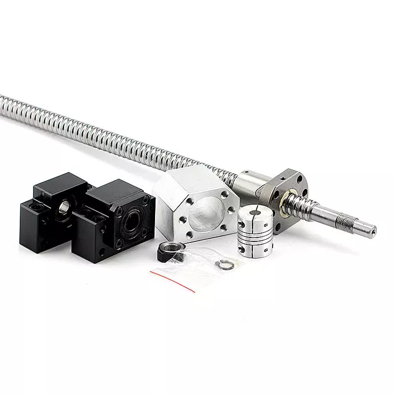
Applications
A ball screw and nut assembly are essential components of a variety of important actuation and control devices. The 2 components rely on the ability of the screw to rotate easily while converting the rotation into precise lateral movement. Ball screws are a common component in computer-controlled motion-control systems. The precision of ball screw rotation is essential for the accurate adjustment of flight control surfaces. In addition, ball screws are important components of wire bonding and computer-controlled motion-control systems.
Ball screws are highly accurate, requiring minimal lead error. The lead error of a screw is the difference between the theoretical and actual distance traveled by the nut during rotation. The lead error of a ball screw depends on several factors, including the manufacturing accuracy of the ball grooves, the compactness of the assembly, and the set-up precision. This error is not constant from lead to lead, but it may be reduced through preloading, lubrication, and increased mounting accuracy.
The ball is urged to move up and down by rotation of the nut, which is preferably a hexagonal shaft. This allows the ball to be raised easily over the land of the screw. It is important to note that the nut has a groove on the outer surface that is deep enough to accommodate a ball. This groove is deep enough to accommodate a ball, and the groove extends the length of the screw, thereby reducing friction and increasing precision.
The recirculated balls in a multi-start ball screw assembly may cross multiple threads and turn in the circuit. Multi-start ball screw assemblies typically use the internal channel method to recirculate balls. This design allows multiple ball nuts to be used in a single nut and can be easily installed. The ball nut and the nut may also be incorporated into several separate circuits. If several recirculation paths are desired, a ball nut and a multi-start system may be used.
Durability
A key feature of ball screws is their durability. During manufacture, a ball screw’s material must be chosen carefully. A corrosion-resistant steel called Cronidur(r) 30 is an ideal choice. Ball screws made from this material are exceptionally reliable in space due to their alternating steel-ceramic architecture. As the conditions of space are extreme, corrosion-resistant materials are essential to ensure optimum performance. CZPT has decades of experience manufacturing high-quality ball screws. Besides providing a complete range of ball screws, the company also offers technological solutions and dedicated components.
CZPT developed a special design for the High-Durability Precision Ball Screw. This design makes it easier to form a thin film of oil on the material’s surface. This oil helps reduce friction and improve the precision of a ball screw. This material’s special microstructure reduces the wear of ball screws and improves their service life. CZPT also aims to improve the wear-resistance of ball screws.
In addition to the axial load, a ball screw’s life rating should be based on the jacking and vertical loads. In other words, if all load balls are in contact with the raceways, the L-10 life rating of ball screw assemblies would be converted to an L-2 life rating. This change would increase the overall reliability of a ball screw to 98%. Then again, it’s important to note that vertical load is the only 1 that would be completely removed from the chart.
In addition to these important considerations, it is essential to operate ball screws within their recommended operating temperature range. Failure to do so could result in thermal expansion of the ball screw, causing positioning errors. To ensure lubrication of the ball screw, it’s important to keep its operating temperature within the recommended range. However, it is possible to operate it at temperatures that are too high. If this occurs, the screw should be sent to the manufacturer for repair.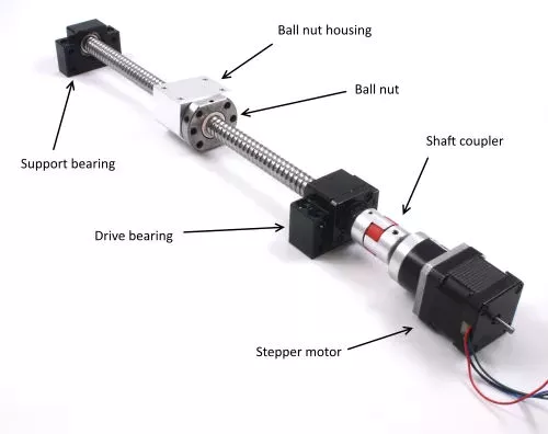
Size
Besides their obvious use, ball screws come in 2 sizes, large and small. Although small balls should not show significant wear, they should still be used to enhance the screw’s durability. This can be difficult to determine because screw rebuilders tend to overlook this aspect. So, what is the best size for ball screws? This article will look at both sizes and what they mean for the screw’s durability. Also, we’ll look at some of the things to keep in mind when choosing the right size for your project.
A ball screw’s size depends on its application and performance requirements. Some types have small diameters and fine leads, while others feature large diameters. High precision applications often require miniature ball screws. Some manufacturers even offer compact ball screws with a smaller outer diameter. The latter is commonly found in miniature designs and feature diameters up to 25 mm. However, this doesn’t mean that a smaller diameter means less accuracy. Regardless of the size, you’ll want to make sure to select a screw that will meet your requirements.
The screw’s root diameter is a critical measurement in determining critical speed and column load calculations. A ball screw’s minor diameter is the minimum dimension of the screw shaft at the bottom of the ball grooves. In addition, the idler ball is a necessary component of a ball screw. It prevents friction between the load and idler balls, but does not carry the load itself. Likewise, the non-operating load capacity should be large enough to prevent the balls from brinelling and plastic deformation.
The characteristic speed is the rotational speed at which the ball screw begins to vibrate due to dynamic load. Inch/imperial screws are specified for 1 million revolutions, while metric screw has a specific limit for 1 million inches of linear travel. Various manufacturing processes have their own ways to calculate the useful life of ball screw assemblies. For example, Precision Grinding produces the lowest lead errors. In addition, the life of a ball screw depends on the length of the screw and the mounting support for the end bearings.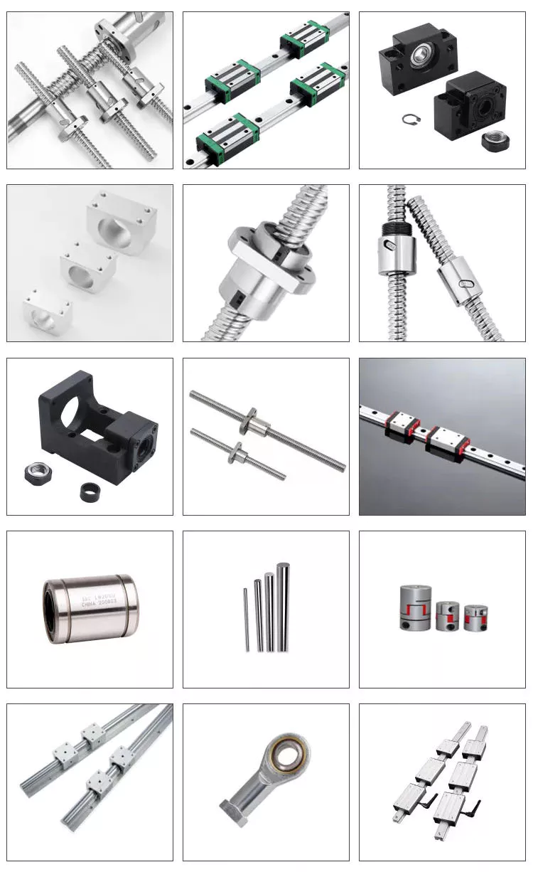
Maintenance
It is critical to regularly perform PM on your ball screw assemblies to ensure optimal performance. A dirty ball screw assembly will result in poor performance and faster wear, so removing dirt from the nut and shaft is a good idea. If there are problems with the ball nut, the lubricant inside can become stripped or the nut can become dirty due to chemical exposure. You should also check for oxidation or corrosion on the contact surfaces of the ball screw, and replace it if necessary.
The first sign of a deteriorating ball screw is excessive vibration. This may be caused by a bent screw shaft or misaligned bearing housings. If it makes noise when running, this may be due to excessive build-up or a broken return tube. Other issues may be caused by endplay in support bearings or excessive preload or improper lubrication. If any of these problems are found, it is essential to perform regular maintenance on the ball screw to prolong its life.
Getting regular maintenance on the ball screw assembly is important. If the screw is not properly maintained, it may wear out prematurely. If this happens, you can contact a ball screw repair service. CZPT International, Inc., a leading supplier of industrial parts, can help you get the screw back into optimal working order or find a new one. A ball screw repair company can help you avoid the inconvenience of downtime and maximize your productivity.
It is essential to properly lubricate a ball screw assembly in order to prolong its life. Lubrication can prevent corrosion and increase the life of the screw by 85 percent. It is important to remember that the type of lubricant you use should correspond to the load applied to the assembly. Lubrication should also be done at regular intervals. Once you’ve established the right amount of lubrication, you can then apply it on the screw.