Tag Archives: cardan shaft

China supplier Tractor Parts Power Cross Joint Cardan CZPT CZPT Transmission Pto Drive Shaft for Agriculture Machinery near me factory

Product Description

Tractor Parts Power Cross Joint Transmission Pto Drive Shaft for Agriculture Machinery Sp48

HangZhou CZPT International Trading Co.,Ltd is a modern enterprise specilizing in the development, production, sales and services of PTO shaft. We adhere to the principle of “Precise Driveline, Advocate Green”, using advanced technology and equipments to ensure all the technical standards of precise driveline. So that the transmission efficiency can be maxmized and every drop of resource of customers’ can be saved. Meanwhile, we have a customer-centric service system, providing a full range of pre-sale, sale and after-sale service. Customer satisfaction is our forever pursuit.

We follow the principle of people first, trying our best to set up a pleasant surroundings and platform of performance for each employee, so everyone can be self-consciously active to join in “Precise Driveline, Adocate Green” to embody the self-worth, enterprise value and social value.

Newnuro’s goal is: reducing customer’s purchase budget, support customers to earn more market.
Newnuro always finds solution for customers.Customer satisfaction is our ultimate goal and forever pursuit.

Mechanical advantages of pulleys

A pulley is a mechanical device used to transmit motion. The device has a variety of uses, including lifting heavy objects. In this article, we will discuss the mechanical advantages, types, common uses and safety considerations of pulleys. We’ll also discuss how to identify pulleys and their components, and what to look out for when using pulleys. Read on to learn more about pulleys.

pulley

Mechanical advantages of pulleys

The mechanical advantage of pulleys is that they change the direction of force from 1 direction to another. In this way, the person lifting the heavy object can change its position with minimal effort. The pulleys are also easy to install and require no lubrication after installation. They are also relatively cheap. Combinations of pulleys and cables can be used to change the direction of the load.
The mechanical advantage of a pulley system increases with the number of ropes used in the system. The more cycles a system has, the more efficient it is. If the system had only 1 rope, the force required to pull the weight would be equal. By adding a second rope, the effort required to pull the weight is reduced. This increase in efficiency is known as the mechanical advantage of the pulley.
Pulleys have many uses. For example, ziplines are 1 application. This is a good example of pulleys in use today. Pulley systems can be complex and require a lot of space. Using ziplines as an example, advanced students can calculate the mechanical advantage of multiple pulleys by dividing the work done by each pulley by the remainder or fraction. Regents at the University of Colorado created a zipline with K-12 input.
Another use for pulleys is weight lifting. This technique is very effective when using multiple strands of rope. A single rope going from 1 pulley to the other with just 2 hands is not enough to lift heavy objects. Using a pulley system will greatly increase the force you receive. This power is multiplied over a larger area. So your lifting force will be much greater than the force exerted by a single rope.
The pulley is a great invention with many uses. For example, when lifting heavy objects, pulleys are a great way to get the job done, and it’s easier to do than 1 person. The pulley is fixed on a hinge and rotates on a shaft or shaft. Then pull the rope down to lift the object. A pulley assembly will make the task easier. In addition, it will also allow power to be transferred from 1 rotary shaft to another.
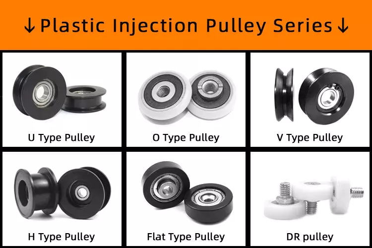
pulley

Types of pulleys

If you are an engineer, you must have come across different types of pulleys. Some pulleys come in multiple types, but a typical pulley has only 1 type. These types of pulleys are used in various industrial processes. Here are some common types of pulleys that engineers encounter on the job. In addition to the above, there are many more. If you haven’t seen them in practice, you can check out a list of the different types below.
Fixed pulleys: Fixed pulleys have a roller attached to a fixed point. The force required to pull the load through the fixed pulley is the same as the force required to lift the object. Movable pulleys allow you to change the direction of the force, for example, by moving it laterally. Likewise, movable pulleys can be used to move heavy objects up and down. Commonly used in multi-purpose elevators, cranes and weight lifters.
Composite pulleys combine fixed and movable pulleys. This combination adds to the mechanical advantage of both systems. It can also change the direction of the force, making it easier to handle large loads. This article discusses the different types of pulleys used for lifting and moving. Braided pulleys are an example of these pulleys. They combine the advantages of both types.
A simple pulley consists of 1 or more wheels, which allow it to reverse the direction of the force used to lift the load. On the other hand, dual-wheel pulleys can help lift twice the weight. By combining multiple materials into 1 pulley, a higher ME will be required. Regardless of the type of pulley, understanding the principles behind it is critical.
Pulleys are an important part of construction and mechanical engineering, and their use dates back to Archimedes. They are a common feature of oil derricks and escalators. The main use of pulleys is to move heavy objects such as boats. In addition to this, they are used in other applications such as extending ladders and lifting heavy objects. The pulley also controls the aircraft rudder, which is important in many different applications.

Commonly used

Common uses for pulleys are varied. Pulley systems are found throughout most areas of the house, from adjustable clotheslines to motor pulleys in different machines. Commercially, 1 of the most common uses is for cranes. Cranes are equipped with pulleys to lift heavy objects. It is also common to use pulley systems in tall buildings, which allow tall buildings to move with relative ease.
Pulleys are commonly used in interception and zipline systems, where a continuous rope around the pulley transmits force. Depending on the application, the rope is either light or strong. Pulleys are formed by wrapping a rope around a set of wheels. The rope pulls the object in the direction of the applied force. Some elevators use this system. Pull a cable on 1 end and attach a counterweight on the other end.
Another common use for pulleys is to move heavy objects. Pulleys mounted on walls, ceilings or other objects can lift heavy objects like heavy toolboxes or 2×4 planks. The device can also be used to transfer power from 1 rotating shaft to another. When used to lift heavy objects, pulleys can be used to help you achieve your goals of a good workout.
Pulley systems have a variety of uses, from the most basic to the most advanced. Its popularity is indisputable and it is used in different industries. A good example is timing belts. These pulleys transmit power to other components in the same direction. They can also be static or dynamic depending on the needs of the machine. In most cases, the pulley system is custom made for the job.
Pulley systems can be simple or complex, but all 3 systems transfer energy efficiently. In most cases, the mechanical advantage of a single pulley is 1 and the mechanical advantage of a single active pulley is 2. On the other hand, a single live pulley only doubles the force. This means you can trade effort for distance. Pulleys are the perfect solution for many common applications.
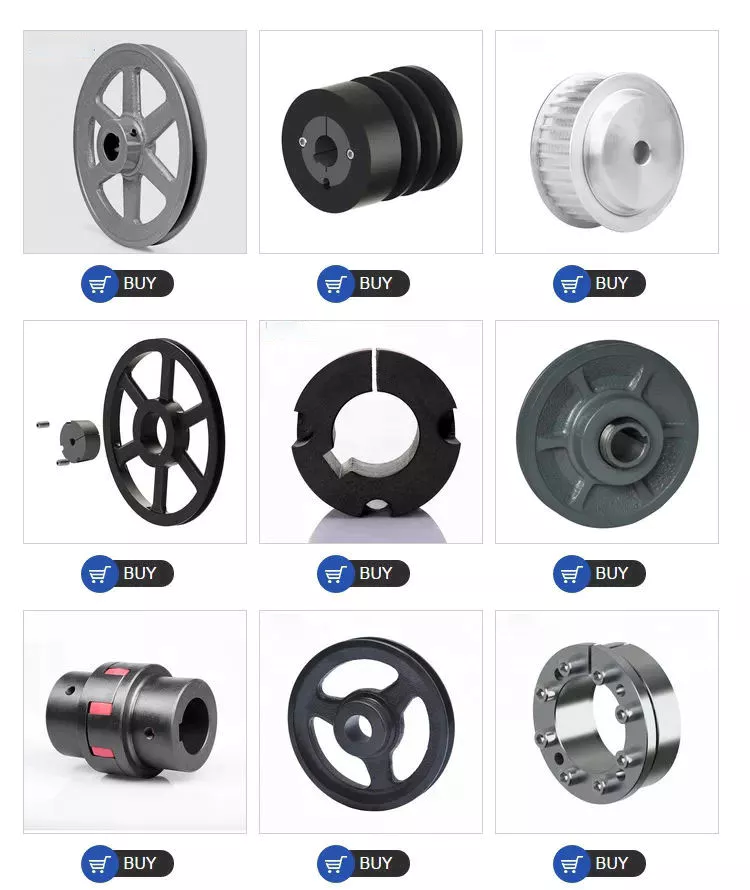
pulley

Safety Notice

If you use pulleys, you need to take some safety precautions. First, make sure you’re wearing the correct protective gear. A hard hat is a must to avoid being hit by falling objects. You may also want to wear gloves for added protection. You should also maintain a good distance from the pulley so that nearby people can walk around it safely.
Another important safety measure to take before using a chain hoist is to barricade the area to be lifted. Use marker lines to prevent the load from sliding when moving horizontally. Finally, use only the sprocket set for vertical lift. Always install shackle pins before lifting. You should also wear personal protective equipment such as earplugs and safety glasses when using the chain hoist.
In addition to these safety measures, you should also use cables made from aerospace-grade nylon. They will last many cycles and are made of high quality materials. Also, make sure the cables are lubricated. These measures reduce friction and corrosion. No matter what industry you are in, be sure to follow these precautions to ensure a long service life for your cables. Consult the cable manufacturer if you are unsure of the appropriate material. A company with 60 years of experience in the cable industry can recommend the right material for your system.

China supplier Tractor Parts Power Cross Joint Cardan CZPT CZPT Transmission Pto Drive Shaft for Agriculture Machinery     near me factory China supplier Tractor Parts Power Cross Joint Cardan CZPT CZPT Transmission Pto Drive Shaft for Agriculture Machinery     near me factory

China Custom Cardan Transmission Tractor Spare Parts CZPT Joint Pto Drive Shaft for Agriculture Machinery Jh50 with Great quality

Product Description

Pto Shaft for Agriculture Machinery Jh50

HangZhou CZPT International Trading Co.,Ltd is a modern enterprise specilizing in the development, production, sales and services of PTO shaft. We adhere to the principle of “Precise Driveline, Advocate Green”, using advanced technology and equipments to ensure all the technical standards of precise driveline. So that the transmission efficiency can be maxmized and every drop of resource of customers’ can be saved. Meanwhile, we have a customer-centric service system, providing a full range of pre-sale, sale and after-sale service. Customer satisfaction is our forever pursuit. 

We follow the principle of people first, trying our best to set up a pleasant surroundings and platform of performance for each employee, so everyone can be self-consciously active to join in “Precise Driveline, Adocate Green” to embody the self-worth, enterprise value and social value. 

Newnuro’s goal is: reducing customer’s purchase budget, support customers to earn more market.
Newnuro always finds solution for customers.Customer satisfaction is our ultimate goal and forever pursuit.


Analytical Approaches to Estimating Contact Pressures in Spline Couplings

A spline coupling is a type of mechanical connection between 2 rotating shafts. It consists of 2 parts – a coupler and a coupling. Both parts have teeth which engage and transfer loads. However, spline couplings are typically over-dimensioned, which makes them susceptible to fatigue and static behavior. Wear phenomena can also cause the coupling to fail. For this reason, proper spline coupling design is essential for achieving optimum performance.
splineshaft

Modeling a spline coupling

Spline couplings are becoming increasingly popular in the aerospace industry, but they operate in a slightly misaligned state, causing both vibrations and damage to the contact surfaces. To solve this problem, this article offers analytical approaches for estimating the contact pressures in a spline coupling. Specifically, this article compares analytical approaches with pure numerical approaches to demonstrate the benefits of an analytical approach.
To model a spline coupling, first you create the knowledge base for the spline coupling. The knowledge base includes a large number of possible specification values, which are related to each other. If you modify 1 specification, it may lead to a warning for violating another. To make the design valid, you must create a spline coupling model that meets the specified specification values.
After you have modeled the geometry, you must enter the contact pressures of the 2 spline couplings. Then, you need to determine the position of the pitch circle of the spline. In Figure 2, the centre of the male coupling is superposed to that of the female spline. Then, you need to make sure that the alignment meshing distance of the 2 splines is the same.
Once you have the data you need to create a spline coupling model, you can begin by entering the specifications for the interface design. Once you have this data, you need to choose whether to optimize the internal spline or the external spline. You’ll also need to specify the tooth friction coefficient, which is used to determine the stresses in the spline coupling model 20. You should also enter the pilot clearance, which is the clearance between the tip 186 of a tooth 32 on 1 spline and the feature on the mating spline.
After you have entered the desired specifications for the external spline, you can enter the parameters for the internal spline. For example, you can enter the outer diameter limit 154 of the major snap 54 and the minor snap 56 of the internal spline. The values of these parameters are displayed in color-coded boxes on the Spline Inputs and Configuration GUI screen 80. Once the parameters are entered, you’ll be presented with a geometric representation of the spline coupling model 20.

Creating a spline coupling model 20

The spline coupling model 20 is created by a product model software program 10. The software validates the spline coupling model against a knowledge base of configuration-dependent specification constraints and relationships. This report is then input to the ANSYS stress analyzer program. It lists the spline coupling model 20’s geometric configurations and specification values for each feature. The spline coupling model 20 is automatically recreated every time the configuration or performance specifications of the spline coupling model 20 are modified.
The spline coupling model 20 can be configured using the product model software program 10. A user specifies the axial length of the spline stack, which may be zero, or a fixed length. The user also enters a radial mating face 148, if any, and selects a pilot clearance specification value of 14.5 degrees or 30 degrees.
A user can then use the mouse 110 to modify the spline coupling model 20. The spline coupling knowledge base contains a large number of possible specification values and the spline coupling design rule. If the user tries to change a spline coupling model, the model will show a warning about a violation of another specification. In some cases, the modification may invalidate the design.
In the spline coupling model 20, the user enters additional performance requirement specifications. The user chooses the locations where maximum torque is transferred for the internal and external splines 38 and 40. The maximum torque transfer location is determined by the attachment configuration of the hardware to the shafts. Once this is selected, the user can click “Next” to save the model. A preview of the spline coupling model 20 is displayed.
The model 20 is a representation of a spline coupling. The spline specifications are entered in the order and arrangement as specified on the spline coupling model 20 GUI screen. Once the spline coupling specifications are entered, the product model software program 10 will incorporate them into the spline coupling model 20. This is the last step in spline coupling model creation.
splineshaft

Analysing a spline coupling model 20

An analysis of a spline coupling model consists of inputting its configuration and performance specifications. These specifications may be generated from another computer program. The product model software program 10 then uses its internal knowledge base of configuration dependent specification relationships and constraints to create a valid three-dimensional parametric model 20. This model contains information describing the number and types of spline teeth 32, snaps 34, and shoulder 36.
When you are analysing a spline coupling, the software program 10 will include default values for various specifications. The spline coupling model 20 comprises an internal spline 38 and an external spline 40. Each of the splines includes its own set of parameters, such as its depth, width, length, and radii. The external spline 40 will also contain its own set of parameters, such as its orientation.
Upon selecting these parameters, the software program will perform various analyses on the spline coupling model 20. The software program 10 calculates the nominal and maximal tooth bearing stresses and fatigue life of a spline coupling. It will also determine the difference in torsional windup between an internal and an external spline. The output file from the analysis will be a report file containing model configuration and specification data. The output file may also be used by other computer programs for further analysis.
Once these parameters are set, the user enters the design criteria for the spline coupling model 20. In this step, the user specifies the locations of maximum torque transfer for both the external and internal spline 38. The maximum torque transfer location depends on the configuration of the hardware attached to the shafts. The user may enter up to 4 different performance requirement specifications for each spline.
The results of the analysis show that there are 2 phases of spline coupling. The first phase shows a large increase in stress and vibration. The second phase shows a decline in both stress and vibration levels. The third stage shows a constant meshing force between 300N and 320N. This behavior continues for a longer period of time, until the final stage engages with the surface.
splineshaft

Misalignment of a spline coupling

A study aimed to investigate the position of the resultant contact force in a spline coupling engaging teeth under a steady torque and rotating misalignment. The study used numerical methods based on Finite Element Method (FEM) models. It produced numerical results for nominal conditions and parallel offset misalignment. The study considered 2 levels of misalignment – 0.02 mm and 0.08 mm – with different loading levels.
The results showed that the misalignment between the splines and rotors causes a change in the meshing force of the spline-rotor coupling system. Its dynamics is governed by the meshing force of splines. The meshing force of a misaligned spline coupling is related to the rotor-spline coupling system parameters, the transmitting torque, and the dynamic vibration displacement.
Despite the lack of precise measurements, the misalignment of splines is a common problem. This problem is compounded by the fact that splines usually feature backlash. This backlash is the result of the misaligned spline. The authors analyzed several splines, varying pitch diameters, and length/diameter ratios.
A spline coupling is a two-dimensional mechanical system, which has positive backlash. The spline coupling is comprised of a hub and shaft, and has tip-to-root clearances that are larger than the backlash. A form-clearance is sufficient to prevent tip-to-root fillet contact. The torque on the splines is transmitted via friction.
When a spline coupling is misaligned, a torque-biased thrust force is generated. In such a situation, the force can exceed the torque, causing the component to lose its alignment. The two-way transmission of torque and thrust is modeled analytically in the present study. The analytical approach provides solutions that can be integrated into the design process. So, the next time you are faced with a misaligned spline coupling problem, make sure to use an analytical approach!
In this study, the spline coupling is analyzed under nominal conditions without a parallel offset misalignment. The stiffness values obtained are the percentage difference between the nominal pitch diameter and load application diameter. Moreover, the maximum percentage difference in the measured pitch diameter is 1.60% under a torque of 5000 N*m. The other parameter, the pitch angle, is taken into consideration in the calculation.

China Custom Cardan Transmission Tractor Spare Parts CZPT Joint Pto Drive Shaft for Agriculture Machinery Jh50     with Great qualityChina Custom Cardan Transmission Tractor Spare Parts CZPT Joint Pto Drive Shaft for Agriculture Machinery Jh50     with Great quality

China Professional OEM/ ODM Tractor Part Pto Drive Cardan Shaft with Free Design Custom

Product Description

OEM ODM Cardan Shaft for Farm Machine and Agriculture Machine

1. Power or torque related to alternating load you require.  

2. Cross journal(Universal joint) size which decides torque of a PTO Shaft:  

3 Closed overall length (or cross to cross) of a PTO shaft.  

4 Tubes or Pipes  

FAQ

1. Q: Are your products forged or cast?

    A: All of our products are forged.

2. Q: Do you have a CE certificate?
    A: Yes, we are CE qualified.
3. Q: What’s the horse power of the pto shaft are available?
    A: We provide a full range of pto shaft, ranging from 16HP-200HP.
4. Q: How many splined specification do you have ?
    A: We produce 1 1/8″-Z6, 1 3/8″-Z6, 1 3/4″-Z6, 1 3/8″- Z21, 1 3/4″-Z20, 8X42X48X8 and 8X32X38X6 splines.
5. Q: How about the warranty?
    A: We guarantee 1 year warranty. With quality problems, we will send you the new products for free within next shipment.
6. Q: What’s your payment terms?
    A: T/T, L/C, D/A, D/P….
7. Q: What is the delivery time?
    A: 30 days after receiving your advanced deposit.
8. Q: What’s your MOQ?
    A: 50 PCS for each type.

Screws and Screw Shafts

A screw is a mechanical device that holds objects together. Screws are usually forged or machined. They are also used in screw jacks and press-fitted vises. Their self-locking properties make them a popular choice in many different industries. Here are some of the benefits of screws and how they work. Also read about their self-locking properties. The following information will help you choose the right screw for your application.

Machined screw shaft

A machined screw shaft can be made of various materials, depending on the application. Screw shafts can be made from stainless steel, brass, bronze, titanium, or iron. Most manufacturers use high-precision CNC machines or lathes to manufacture these products. These products come in many sizes and shapes, and they have varying applications. Different materials are used for different sizes and shapes. Here are some examples of what you can use these screws for:
Screws are widely used in many applications. One of the most common uses is in holding objects together. This type of fastener is used in screw jacks, vises, and screw presses. The thread pitch of a screw can vary. Generally, a smaller pitch results in greater mechanical advantage. Hence, a machined screw shaft should be sized appropriately. This ensures that your product will last for a long time.
A machined screw shaft should be compatible with various threading systems. In general, the ASME system is used for threaded parts. The threaded hole occupies most of the shaft. The thread of the bolt occupy either part of the shaft, or the entire one. There are also alternatives to bolts, including riveting, rolling pins, and pinned shafts. These alternatives are not widely used today, but they are useful for certain niche applications.
If you are using a ball screw, you can choose to anneal the screw shaft. To anneal the screw shaft, use a water-soaked rag as a heat barrier. You can choose from 2 different options, depending on your application. One option is to cover the screw shaft with a dust-proof enclosure. Alternatively, you can install a protective heat barrier over the screw shaft. You can also choose to cover the screw shaft with a dust-proof machine.
If you need a smaller size, you can choose a smaller screw. It may be smaller than a quarter of an inch, but it may still be compatible with another part. The smaller ones, however, will often have a corresponding mating part. These parts are typically denominated by their ANSI numerical size designation, which does not indicate threads-per-inch. There is an industry standard for screw sizes that is a little easier to understand.
screwshaft

Ball screw nut

When choosing a Ball screw nut for a screw shaft, it is important to consider the critical speed of the machine. This value excites the natural frequency of a screw and determines how fast it can be turned. In other words, it varies with the screw diameter and unsupported length. It also depends on the screw shaft’s diameter and end fixity. Depending on the application, the nut can be run at a maximum speed of about 80% of its theoretical critical speed.
The inner return of a ball nut is a cross-over deflector that forces the balls to climb over the crest of the screw. In 1 revolution of the screw, a ball will cross over the nut crest to return to the screw. Similarly, the outer circuit is a circular shape. Both flanges have 1 contact point on the ball shaft, and the nut is connected to the screw shaft by a screw.
The accuracy of ball screws depends on several factors, including the manufacturing precision of the ball grooves, the compactness of the assembly, and the set-up precision of the nut. Depending on the application, the lead accuracy of a ball screw nut may vary significantly. To improve lead accuracy, preloading, and lubrication are important. Ewellix ball screw assembly specialists can help you determine the best option for your application.
A ball screw nut should be preloaded prior to installation in order to achieve the expected service life. The smallest amount of preload required can reduce a ball screw’s calculated life by as much as 90 percent. Using a lubricant of a standard grade is recommended. Some lubricants contain additives. Using grease or oil in place of oil can prolong the life of the screw.
A ball screw nut is a type of threaded nut that is used in a number of different applications. It works similar to a ball bearing in that it contains hardened steel balls that move along a series of inclined races. When choosing a ball screw nut, engineers should consider the following factors: speed, life span, mounting, and lubrication. In addition, there are other considerations, such as the environment in which the screw is used.
screwshaft

Self-locking property of screw shaft

A self-locking screw is 1 that is capable of rotating without the use of a lock washer or bolt. This property is dependent on a number of factors, but 1 of them is the pitch angle of the thread. A screw with a small pitch angle is less likely to self-lock, while a large pitch angle is more likely to spontaneously rotate. The limiting angle of a self-locking thread can be calculated by calculating the torque Mkdw at which the screw is first released.
The pitch angle of the screw’s threads and its coefficient of friction determine the self-locking function of the screw. Other factors that affect its self-locking function include environmental conditions, high or low temperature, and vibration. Self-locking screws are often used in single-line applications and are limited by the size of their pitch. Therefore, the self-locking property of the screw shaft depends on the specific application.
The self-locking feature of a screw is an important factor. If a screw is not in a state of motion, it can be a dangerous or unusable machine. The self-locking property of a screw is critical in many applications, from corkscrews to threaded pipe joints. Screws are also used as power linkages, although their use is rarely necessary for high-power operations. In the archimedes’ screw, for example, the blades of the screw rotate around an axis. A screw conveyor uses a rotating helical chamber to move materials. A micrometer uses a precision-calibrated screw to measure length.
Self-locking screws are commonly used in lead screw technology. Their pitch and coefficient of friction are important factors in determining the self-locking property of screws. This property is advantageous in many applications because it eliminates the need for a costly brake. Its self-locking property means that the screw will be secure without requiring a special kind of force or torque. There are many other factors that contribute to the self-locking property of a screw, but this is the most common factor.
Screws with right-hand threads have threads that angle up to the right. The opposite is true for left-hand screws. While turning a screw counter-clockwise will loosen it, a right-handed person will use a right-handed thumb-up to turn it. Similarly, a left-handed person will use their thumb to turn a screw counter-clockwise. And vice versa.
screwshaft

Materials used to manufacture screw shaft

Many materials are commonly used to manufacture screw shafts. The most common are steel, stainless steel, brass, bronze, and titanium. These materials have advantages and disadvantages that make them good candidates for screw production. Some screw types are also made of copper to fight corrosion and ensure durability over time. Other materials include nylon, Teflon, and aluminum. Brass screws are lightweight and have aesthetic appeal. The choice of material for a screw shaft depends on the use it will be made for.
Shafts are typically produced using 3 steps. Screws are manufactured from large coils, wire, or round bar stock. After these are produced, the blanks are cut to the appropriate length and cold headed. This cold working process pressudes features into the screw head. More complicated screw shapes may require 2 heading processes to achieve the desired shape. The process is very precise and accurate, so it is an ideal choice for screw manufacturing.
The type of material used to manufacture a screw shaft is crucial for the function it will serve. The type of material chosen will depend on where the screw is being used. If the screw is for an indoor project, you can opt for a cheaper, low-tech screw. But if the screw is for an outdoor project, you’ll need to use a specific type of screw. This is because outdoor screws will be exposed to humidity and temperature changes. Some screws may even be coated with a protective coating to protect them from the elements.
Screws can also be self-threading and self-tapping. The self-threading or self-tapping screw creates a complementary helix within the material. Other screws are made with a thread which cuts into the material it fastens. Other types of screws create a helical groove on softer material to provide compression. The most common uses of a screw include holding 2 components together.
There are many types of bolts available. Some are more expensive than others, but they are generally more resistant to corrosion. They can also be made from stainless steel or aluminum. But they require high-strength materials. If you’re wondering what screws are, consider this article. There are tons of options available for screw shaft manufacturing. You’ll be surprised how versatile they can be! The choice is yours, and you can be confident that you’ll find the screw shaft that will best fit your application.

China Professional OEM/ ODM Tractor Part Pto Drive Cardan Shaft     with Free Design CustomChina Professional OEM/ ODM Tractor Part Pto Drive Cardan Shaft     with Free Design Custom

China OEM air blower dynamic balancing machine cardan shaft balancer with Free Design Custom

Warranty: 1 yr, One particular 12 months
Tailored assist: ODM
Model Amount: YYW-ten thousand/20000
Energy: Electronic
Motor Energy: 22KW-55KW variable-frequency
Duration: 3400mm
Width: 850mm
Peak: 2100mm
Gross Bodyweight: 3900kg
Delivery time: inside of forty times
Merchandise: Universal Joint Generate Balancing Equipment
Web site:
Certification: CE
Packaging Specifics: Universal Joint Travel Balancing Machine Fumigated Wooden Box
Port: China

air blower dynamic balancing device cardan shaft balancer1. Unique developed brackets can successfully transmit mechanical force2. The tough and reliable sensor possesses substantial sensitivity3. The everlasting calibration brings higher accuracy4. Driven by universal coupling,transmit the electrical power steadily5. Relevant to rotors which can’ Automobile Crankshaft Pulley 11237573655 Vibration Damper F30 F34 F07 F10 F01 F02 X3 X5 Engine Crankshaft Pulley t be driven by belt or need huge power6. Innovative electrical measuring technique and pleasant man-equipment interface7.PHW series are relevant for blower, huge-sized motor, pump, LTWOO UT Bicycle Ceramic Bearing Carbon Fiber Jockey Pulley Wheel Established Rear Derailleurs Xihu (West Lake) Dis. Wheel 11 Pace 34T CZPT wheel centrifuge, rubber roller, drying cylinder, TQG 5-Axis robotic arm harmonic push gearbox CSG-fourteen-fifty-2UH pace reducer factory Reductor internal-combustion engine and so forth

Specialized ParametersYYW-10000YYW-20000Workpiece good quality selection(kg)100571000Maximum workpiece diameter(mm)Φ3000Distance in between 2 seats(mm)Min320Min450Support shaft diameter range(mm)Φ60~400Distance from coupling flange of drive shaft to heart of farthest bearing(mm)40005000Motor Electricity(kw)2255Universal Coupling Torque(N.m)22505000Minimum reachable residual imbalance(emar)≤ NMRV110 Velocity reduction worm gearbox reducer 1g.mm/kgCompany Info

In depth Photos

Packaging & Delivery

FAQ

What is a drive shaft?

If you notice a clicking sound whilst driving, it is most likely the driveshaft. An seasoned auto mechanic will be able to explain to you if the sounds is coming from the two sides or from a single side. If it only occurs on one aspect, you need to check it. If you notice sounds on each sides, you need to contact a mechanic. In either case, a substitute driveshaft ought to be easy to locate.
air-compressor

The push shaft is a mechanical part

A driveshaft is a mechanical device that transmits rotation and torque from the motor to the wheels of the vehicle. This part is essential to the operation of any driveline, as the mechanical energy from the motor is transmitted to the PTO (electricity take-off) shaft, which hydraulically transmits that electricity to related products. Distinct drive shafts include distinct combos of joints to compensate for changes in shaft length and angle. Some sorts of travel shafts incorporate connecting shafts, inside constant velocity joints, and exterior mounted joints. They also incorporate anti-lock method rings and torsional dampers to avoid overloading the axle or leading to the wheels to lock.
Even though driveshafts are fairly gentle, they require to take care of a good deal of torque. Torque used to the push shaft produces torsional and shear stresses. Simply because they have to withstand torque, these shafts are developed to be lightweight and have tiny inertia or excess weight. For that reason, they usually have a joint, coupling or rod among the two areas. Parts can also be bent to accommodate adjustments in the distance between them.
The drive shaft can be created from a assortment of components. The most frequent substance for these elements is steel, although alloy steels are typically employed for high-power applications. Alloy steel, chromium or vanadium are other materials that can be used. The sort of substance utilised relies upon on the application and dimension of the component. In many situations, metal driveshafts are the most resilient and cheapest choice. Plastic shafts are utilised for light-weight duty apps and have distinct torque ranges than steel shafts.

It transfers electrical power from the motor to the wheels

A car’s powertrain is made up of an electrical motor, transmission, and differential. Each and every segment performs a specific occupation. In a rear-wheel travel motor vehicle, the electrical power created by the motor is transmitted to the rear tires. This arrangement increases braking and managing. The differential controls how a lot electrical power every single wheel gets. The torque of the engine is transferred to the wheels in accordance to its velocity.
The transmission transfers electrical power from the motor to the wheels. It is also known as “transgender”. Its task is to guarantee energy is delivered to the wheels. Electrical autos can not generate themselves and need a gearbox to drive forward. It also controls how much power reaches the wheels at any presented second. The transmission is the previous part of the power transmission chain. Even with its many names, the transmission is the most complicated component of a car’s powertrain.
The driveshaft is a extended steel tube that transmits mechanical power from the transmission to the wheels. Cardan joints hook up to the drive shaft and supply flexible pivot details. The differential assembly is mounted on the drive shaft, making it possible for the wheels to flip at different speeds. The differential enables the wheels to change at distinct speeds and is really important when cornering. Axles are also essential to the performance of the auto.

It has a rubber boot that shields it from dust and moisture

To hold this boot in excellent problem, you ought to clean it with chilly water and a rag. Never location it in the dryer or in direct daylight. Warmth can deteriorate the rubber and lead to it to shrink or crack. To prolong the existence of your rubber boots, use rubber conditioner to them often. Indigenous peoples in the Amazon region accumulate latex sap from the bark of rubber trees. Then they put their ft on the fireplace to solidify the sap.
air-compressor

it has a U-shaped connector

The travel shaft has a U-joint that transfers rotational vitality from the motor to the axle. Defective gimbal joints can trigger vibrations when the vehicle is in motion. This vibration is usually mistaken for a wheel balance issue. Wheel equilibrium problems can cause the motor vehicle to vibrate while driving, even though a U-joint failure can cause the motor vehicle to vibrate when decelerating and accelerating, and end when the automobile is stopped.
The travel shaft is linked to the transmission and differential utilizing a U-joint. It allows for modest adjustments in place amongst the two elements. This stops the differential and transmission from remaining flawlessly aligned. The U-joint also enables the travel shaft to be related unconstrained, permitting the car to shift. Its major objective is to transmit electric power. Of all kinds of elastic couplings, U-joints are the oldest.
Your vehicle’s U-joints should be inspected at the very least twice a yr, and the joints need to be greased. When checking the U-joint, you ought to hear a boring seem when changing gears. A clicking sound suggests inadequate grease in the bearing. If you hear or really feel vibrations when shifting gears, you might need to have to support the bearings to extend their lifestyle.

it has a slide-in tube

The telescopic layout is a present day option to conventional driveshaft designs. This modern design and style is dependent on an unconventional design and style philosophy that brings together improvements in content science and manufacturing processes. Consequently, they are far more effective and lighter than typical styles. Slide-in tubes are a basic and effective design resolution for any automobile application. Right here are some of its benefits. Go through on to discover why this sort of shaft is ideal for a lot of programs.
The telescopic generate shaft is an essential component of the standard automobile transmission program. These driveshafts permit linear motion of the two parts, transmitting torque and rotation throughout the vehicle’s driveline. They also absorb strength if the motor vehicle collides. Frequently referred to as foldable driveshafts, their reputation is right dependent on the evolution of the automotive business.
air-compressor

It utilizes a bearing press to change worn or broken U-joints

A bearing push is a gadget that makes use of a rotary press system to set up or take away worn or destroyed U-joints from a push shaft. With this resource, you can exchange worn or destroyed U-joints in your vehicle with relative simplicity. The first action entails positioning the travel shaft in the vise. Then, use the eleven/sixteen” socket to press the other cup in considerably sufficient to install the clips. If the cups will not fit, you can use a bearing press to take away them and repeat the procedure. Right after removing the U-joint, use a grease nipple Make positive the new grease nipple is installed properly.
Worn or damaged U-joints are a key supply of driveshaft failure. If a single of them have been damaged or destroyed, the entire driveshaft could dislocate and the car would lose power. Unless you have a expert mechanic doing the repairs, you will have to change the total driveshaft. The good news is, there are many techniques to do this your self.
If any of these warning signs look on your vehicle, you need to think about replacing the broken or worn U-joint. Common signs of ruined U-joints consist of rattling or periodic squeaking when moving, rattling when shifting, wobbling when turning, or rusted oil seals. If you notice any of these indicators, just take your vehicle to a competent mechanic for a full inspection. Neglecting to change a worn or ruined u-joint on the driveshaft can result in pricey and unsafe repairs and can trigger important damage to your automobile.

China OEM air blower dynamic balancing machine cardan shaft balancer  with Free Design CustomChina OEM air blower dynamic balancing machine cardan shaft balancer  with Free Design Custom